


4.2 Machine function
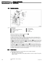
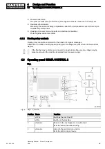
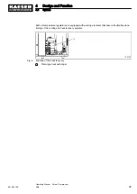
Fig. 4 Machine layout
1
Inlet valve
2
Minimum pressure/check valve
3
Compressor motor
4
Oil filter
5
Airend
6
Control cabinet
7
Oil separator tank
8
Air filter
9
Oil/air cooler
Ambient air is cleaned as it is drawn in through the filter
8
.
The air is then compressed in the airend
5
.
The airend is driven by an electric motor
3
.
Cooling oil is injected into the airend. It lubricates moving parts and forms a seal between the ro‐
tors themselves and between them and the airend casing. This direct cooling in the compression
chamber ensures a very low airend discharge temperature.
Cooling oil recovered from the compressed air in the oil separator tank
7
gives up its heat in the oil
cooler
9
. The oil then flows through the oil filter
4
and back to the point of injection. Pressure with‐
in the machine keeps the oil circulating. A separate pump is not necessary. A thermostatic valve
maintains optimum cooling oil temperature.
Compressed air, freed of cooling oil in the oil separator tank
7
, flows through the minimum pres‐
sure / check valve
2
into the air cooler
9
. The minimum pressure / check valve ensures that there
is always a minimum internal pressure sufficient to maintain cooling oil circulation in the machine.
The aftercooler brings down the compressed air temperature to 5K to 10K above ambient. Most of
the moisture carried in the air is removed in the aftercooler.
4.2.1 Safety devices
The following safety devices are provided and must not be modified or disabled.
■ EMERGENCY STOP control device:
Stops the machine immediately in an emergency situation. The motor is stopped. The pressure
system is vented.
4
Design and Function
4.2
Machine function
30
Operating Manual Screw Compressor
ASK
901824 12 E
Содержание ASK 28
Страница 2: ...Original instructions KKW SASK 2 22 en SBA SCHRAUBEN SC2IO KKW SSC 2 08 20170919 084918...
Страница 6: ...Contents iv Operating Manual Screw Compressor ASK 901824 12 E...
Страница 8: ...List of Illustrations vi Operating Manual Screw Compressor ASK 901824 12 E...
Страница 104: ...13 Annex 13 1 Pipeline and instrument flow diagram P I diagram 94 Operating Manual Screw Compressor ASK 901824 12 E...
Страница 105: ...13 Annex 13 1 Pipeline and instrument flow diagram P I diagram 901824 12 E Operating Manual Screw Compressor ASK 95...
Страница 106: ...13 Annex 13 1 Pipeline and instrument flow diagram P I diagram 96 Operating Manual Screw Compressor ASK 901824 12 E...
Страница 107: ...13 Annex 13 1 Pipeline and instrument flow diagram P I diagram 901824 12 E Operating Manual Screw Compressor ASK 97...
Страница 108: ...13 Annex 13 1 Pipeline and instrument flow diagram P I diagram 98 Operating Manual Screw Compressor ASK 901824 12 E...
Страница 115: ...13 3 Dimensional drawing 13 Annex 13 3 Dimensional drawing 901824 12 E Operating Manual Screw Compressor ASK 105...
Страница 118: ...13 4 Electrical Diagram 13 Annex 13 4 Electrical Diagram 108 Operating Manual Screw Compressor ASK 901824 12 E...
Страница 138: ...13 Annex 13 4 Electrical Diagram 128 Operating Manual Screw Compressor ASK 901824 12 E...


