


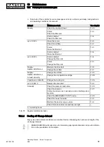


To be checked
See
chapter
Confirmed?
➤ Is there sufficient cooling oil in the separator tank?
(Cooling oil level indicator outside the red zone)
➤ Sufficient cooling oil in the airend?
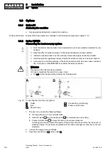
➤ Machine firmly anchored to the floor?
(Option H1)
➤ Are all access doors closed and latched and removable panels in
place and secured?
–
Tab. 50 Installation conditions checklist
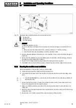
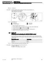
7.4 Setting the overload protection cut-out
Electrical diagram 13.4 gives the location of the overload relay.
With star-delta starting, the phase current is fed via the overload relay. This phase current is 0.58-
times the rated motor current.
To prevent the overload relay being triggered by voltage fluctuations, temperature influences or
component tolerances, the setting can be higher than the arithmetical phase current.
➤ Check the settings of the overload relay.
The overload relay shuts the machine down despite being correctly set?
➤ Contact the authorised KAESER SERVICE.
7.5 Setting the motor overload protection switch
Electrical diagram in chapter 13.4 gives the setting values for the motor overload protection switch.
In direct on-line starting, the current for the fan motor is fed via the motor overload protection
switch.
To prevent the motor overload protection switch from being triggered by voltage fluctuations,
temperature influences or component tolerances, the setting can be higher than the rated
motor current.
➤ Check the motor overload protection switch setting.
The overload protection switch shuts the machine down despite being correctly set?
➤ Contact the authorised KAESER SERVICE.
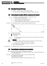
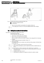
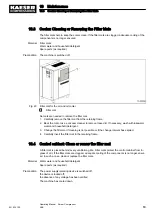
7.6 Pouring cooling oil into the airend
Before starting the compressor for the very first time and before re-starting after a shutdown period
of more than 3 months it is necessary to manually add a quantity of cooling oil into the airend. In
order to avoid that the cooling oil exceeds the permissible level, drain the required quantity from
the de-pressurised oil separator tank.
Chapter 10.16 provides detailed information on how to drain cooling oil from the oil separator tank.
7
Initial Start-up
7.4
Setting the overload protection cut-out
48
Operating Manual Screw Compressor
ASK
901824 12 E
Содержание ASK 28
Страница 2: ...Original instructions KKW SASK 2 22 en SBA SCHRAUBEN SC2IO KKW SSC 2 08 20170919 084918...
Страница 6: ...Contents iv Operating Manual Screw Compressor ASK 901824 12 E...
Страница 8: ...List of Illustrations vi Operating Manual Screw Compressor ASK 901824 12 E...
Страница 104: ...13 Annex 13 1 Pipeline and instrument flow diagram P I diagram 94 Operating Manual Screw Compressor ASK 901824 12 E...
Страница 105: ...13 Annex 13 1 Pipeline and instrument flow diagram P I diagram 901824 12 E Operating Manual Screw Compressor ASK 95...
Страница 106: ...13 Annex 13 1 Pipeline and instrument flow diagram P I diagram 96 Operating Manual Screw Compressor ASK 901824 12 E...
Страница 107: ...13 Annex 13 1 Pipeline and instrument flow diagram P I diagram 901824 12 E Operating Manual Screw Compressor ASK 97...
Страница 108: ...13 Annex 13 1 Pipeline and instrument flow diagram P I diagram 98 Operating Manual Screw Compressor ASK 901824 12 E...
Страница 115: ...13 3 Dimensional drawing 13 Annex 13 3 Dimensional drawing 901824 12 E Operating Manual Screw Compressor ASK 105...
Страница 118: ...13 4 Electrical Diagram 13 Annex 13 4 Electrical Diagram 108 Operating Manual Screw Compressor ASK 901824 12 E...
Страница 138: ...13 Annex 13 4 Electrical Diagram 128 Operating Manual Screw Compressor ASK 901824 12 E...


