


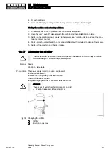


5. Slowly open the shut-off valve
7
and allow cooling oil and air to escape completely until the
pressure gauge reads 0 bar.
6. Close the shut-off valve
3
and unplug the male hose fitting.
➤ Dispose of used oil in accordance with environment protection regulations.
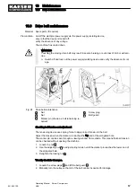
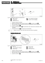
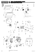
Draining the oil from the airend
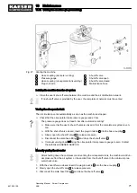
Fig. 32 Changing the cooling oil Compressor block
2
Hose coupling (oil drainage)
3
Shut-off valve
4
Screw plug
5
Belt guard
6
Plug-in nozzle
7
Shut-off valve
8
Maintenance hose
9
Belt pulley
1. Prepare a cooling oil receptacle.
2. With the shut-off valve closed, insert the plug-in nozzle
6
into the hose coupling
2
.
3. Place the other end of the maintenance hose in the oil receptacle and secure it in place.
4. Open the shut-off valves
3
and
7
.
5. Loosen the screw plugs
4
and lift the belt guard
5
.
6. Rotate the pulley
9
for at least five times to ensure that the entire cooling oil has drained off.
7. Replace the belt guard and tighten the screw plugs.
8. Close the shut-off valve
3
and unplug the male hose fitting.
Result The cooling oil is drained from the airend.
A small amount of cooling oil may flow back into the oil separator tank as a result of turning the
pulley.
Repeat the procedure for draining oil from the separator tank to remove this oil.
➤ Dispose of used oil in accordance with environment protection regulations.
10 Maintenance
10.16 Changing the cooling oil
901824 12 E
Operating Manual Screw Compressor
ASK
77
Содержание ASK 28
Страница 2: ...Original instructions KKW SASK 2 22 en SBA SCHRAUBEN SC2IO KKW SSC 2 08 20170919 084918...
Страница 6: ...Contents iv Operating Manual Screw Compressor ASK 901824 12 E...
Страница 8: ...List of Illustrations vi Operating Manual Screw Compressor ASK 901824 12 E...
Страница 104: ...13 Annex 13 1 Pipeline and instrument flow diagram P I diagram 94 Operating Manual Screw Compressor ASK 901824 12 E...
Страница 105: ...13 Annex 13 1 Pipeline and instrument flow diagram P I diagram 901824 12 E Operating Manual Screw Compressor ASK 95...
Страница 106: ...13 Annex 13 1 Pipeline and instrument flow diagram P I diagram 96 Operating Manual Screw Compressor ASK 901824 12 E...
Страница 107: ...13 Annex 13 1 Pipeline and instrument flow diagram P I diagram 901824 12 E Operating Manual Screw Compressor ASK 97...
Страница 108: ...13 Annex 13 1 Pipeline and instrument flow diagram P I diagram 98 Operating Manual Screw Compressor ASK 901824 12 E...
Страница 115: ...13 3 Dimensional drawing 13 Annex 13 3 Dimensional drawing 901824 12 E Operating Manual Screw Compressor ASK 105...
Страница 118: ...13 4 Electrical Diagram 13 Annex 13 4 Electrical Diagram 108 Operating Manual Screw Compressor ASK 901824 12 E...
Страница 138: ...13 Annex 13 4 Electrical Diagram 128 Operating Manual Screw Compressor ASK 901824 12 E...


