↻
Suitable string fuse has been selected.
↻
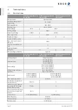
NOTE: DC fuses can be ordered from our customer service team. Use PV fuses
only.
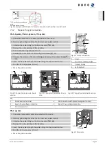
1 Open the individual DC fuse holders one after another.
2 Insert DC fuse of the same type into the fuse holder.
3 Ensure the DC fuse holder is completely closed after fitting.
»
Fuse holders are fitted with fuses. Proceed with testing the earth leakage.
1
2
Fig. 28:
Insert DC fuse
1
Fuse holder
2
DC fuse
7.6.3
Checking the PV generator for a ground fault
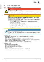
DANGER
Risk of fatal injury due to electric shock!
Severe injury or death will result if the live connections are touched. When there is sunlight present on the
PV generator, there is DC voltage on the open ends of the DC cables.
›
Only touch the PV generator cables on the insulation. Do not touch the exposed ends of the cables.
›
Avoid short circuits.
›
Do not connect any strings with a ground fault to the device.
NOTE
The threshold value from which the insulation monitor reports an error can be set in the
“Parameters”
menu.
Ensure that there is no ground fault
1 Measure the DC voltage between the protective earth (PE) and the positive cable of the PV generator.
2 Measure the DC voltage between the protective earth (PE) and the negative cable of the PV generator.
ð
If stable voltages can be measured, there is a ground fault in the DC generator or its wiring. The ratio between
the measured voltages gives an indication as to the location of this fault.
3 Rectify any faults before taking further measurements.
4 Measure the electrical resistance between the protective earth (PE) and the positive cable of the PV generator.
5 Measure the electrical resistance between the protective earth (PE) and the negative cable of the PV generator.
ð
In addition, ensure that the PV generator has a total insulation resistance of more than 2.0 MOhm, since the
device will not feed in if the insulation resistance is too low.
6 Rectify any faults before connecting the DC generator.
7.6.4
Designing the PV generator
NOTE
Type and configuration of the PV modules.
Connected PV modules must be dimensioned for the DC system voltage in accordance with IEC 61730 Class
A, but at least for the value of the AC grid voltage
NOTE
Sizing of the PV generator
The device is designed with a reserve of DC short-circuit current withstand capability. This allows oversizing
of the connected PV generator. The absolute limit for the PV generator is the value of the maximum short
circuit current (lsc max) and maximum open circuit voltage (Uoc max).
Kaco blueplanet 29.0TL3
Page 26
EN

