RS485
Ethernet
A B
GND
A B
GND
H L
H L
USB
ERR
Optional
INV
OFF
Optional
Optional
DIP
2
1
3
4
5
6
7
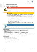
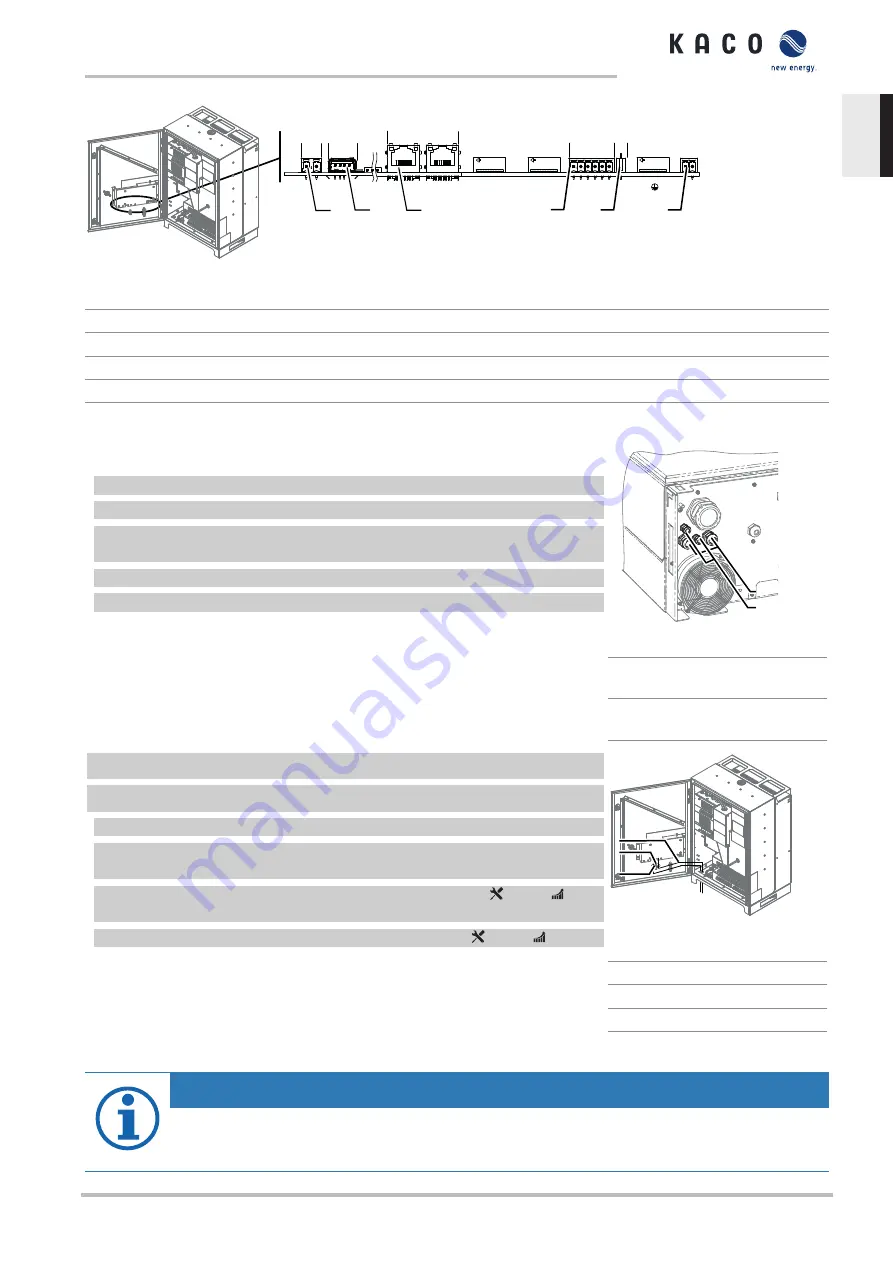
Fig. 33: Communication circuit board: Connection and assignment of the interfaces
1
Communication circuit board
5
RS485 – Connection for data loggers
2
ERR – Connection for fault signal relay
6
DIP switch – Activate terminator
3
USB – Connection for update
7
INV OFF – Connection for remote controls
4
Ethernet – Connection for communication
7.9.2
Insert and lay the cables
Insert the interface cables
1 Unfasten and remove the cover on the cable fitting [W_29/W_20].
2 Remove the sealing insert.
3 Pass the connection cable through the cover of the cable fitting and the sealing
insert.
4 Insert the sealing insert into the cable fitting.
5 Feed the connection cables into the connection area.
»
Proceed with the connection.
1
2
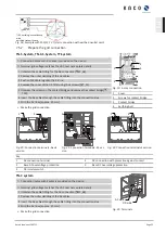
Fig. 34:
Insert the Ethernet cable
1
Cable fitting for pass the Eth-
ernet cable
2
Cable fitting for pass the sig-
nal cable
↻
Housing doors open.
↻
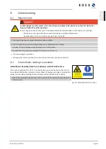
Lay the signal line as per the illustration above.
1 Fix the encased signal cable to the threaded stud bolts.
2 Lay all the interface cables so that they are not under tension and the housing
door has a full range of motion.
3 Secure the cable pass for feeding through the Ethernet cable [ W_20 / 4
Nm].
4 Secure the cable pass for feeding through the signal cable [ W_20 / 1.5 Nm].
»
Proceed with the connection of the cables.
1
2
3
Fig. 35:
Lay the cables for interfaces
1
Signal cable
2
Threaded stud bolts
3
Cable ties
7.9.3
Ethernet connection
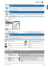
NOTE
The connection plug of an RJ45 cable is larger than the opening of an M25 cable fitting when it is installed.
For this reason, remove the sealing insert before installation and thread the Ethernet cable outside of the
cable fitting through the sealing insert.
Kaco blueplanet 29.0TL3
Page 29
EN


