background image

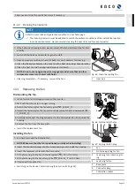
Switch off DC power supply externally via the combiner box (not supplied) using
the DC isolator switch.

Ensure that there is absolutely no DC voltage present.

1 Remove the protection against contact from the PV+ and PV- terminal.

2 Detach the DC cables from the PV+ and PV- terminals.

3 Loosen the cable fitting and pull the PV cable through the cable fitting.

4 Mount the protection against contact on the PV+ and PV- terminal.

5 Place protective caps on the ends of the DC cables.

PV +

PV- PV +

PV-

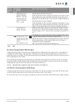
Fig. 70: 

Disconnecting DC cables

11.8

Faults

11.8.1

Procedure

 DANGER

Lethal voltages are still present in the connections and cables of the device even after the device has
been switched off and disconnected!

Severe injuries or death may occur if the cables and/or terminals/busbars in the device are touched.

If a fault occurs, notify an appropriately authorized and qualified electrician or KACO new energy
GmbH Service.

The operator can only carry out actions marked with a B.

NOTE

In case of power failure, wait for the system to automatically restart. Notify your electrician if there is an
extended power failure.

11.8.2

Rectifying a fault

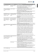
Fault

Possible cause

Explanation/remedy

By

The display is blank and
the LEDs do not light up

Grid voltage not avail-
able

› Check whether the DC and AC voltages are within the permit-
ted limits (see Technical Data)

E

› Notify KACO Service.

E

The device stops feeding
into the grid shortly
after being switched on,
even though there is
sunlight present.

Faulty grid separation
relay in the device.

If the grid separation relay is defective, the device will recog-
nise this error during the self-test.

K

› Ensure that there is sufficient PV generator power.

› If the grid separation relay is defective, have it replaced by
KACO Service.

› Notify KACO Service.

E

Device is active but is
not feeding into the grid.
The display indicates a
grid failure.

Grid-feed is interrupted
due to a grid fault.

Due to a grid fault (over/undervoltage, over/underfrequency),
the device stopped the feed-in process and disconnected from
the grid for safety reasons.

› Change the grid parameters within the permitted operating
limits (see the "Start-Up" section).

E

The grid fuse trips.

The grid fuse capacity is
too low.

In case of a high level of solar radiation, the inverter exceeds its
rated current for a short period, depending on the PV gener-
ator.

Select the capacity of the device’s backup fuse to be somewhat
higher than the maximum feed-in current (see the "Installa-
tion" section).

E

› Contact the grid operator if the grid failure continues to oc-
cur.

E

Kaco blueplanet 29.0TL3

Page 78

EN

Содержание blueplanet 29.0 TL3 M1 OD II4S

Страница 1: ...an original S Basic M L XL Kaco blueplanet 29 0TL3 These instructions form part of the product and must be carefully read observed and stored in a place which is freely accessible at all times Authori...

Страница 2: ...ons contact your system integrator http www kaco newenergy com Definitions on product designations In these operating instructions the product Photovoltaic feed in inverter is referred to as device fo...

Страница 3: ...g the interfaces 28 7 10 Sealing the connection area 32 8 Commissioning 33 8 1 Requirements 33 8 2 Preconditions relating to standards 33 9 Configuration and operation 34 9 1 Initial start up 34 9 2 C...

Страница 4: ...rt no KACO blueplanet 29 0 TL3 M1 OD II4S 1001724 KACO blueplanet 29 0 TL3 M1 OD II4M 1001663 KACO blueplanet 29 0 TL3 M1 OD II4X 1001664 1 2 More information Links to more detailed information can be...

Страница 5: ...Additional information symbols NOTE Useful information and notes Information that is important for a specific topic or objective but that is not safety relevant 1 3 4 Symbols for instructions Prerequ...

Страница 6: ...the document may only be carried out by specially trained personnel with the following qualific ations Knowledge about how an inverter functions and operates Training in the handling of hazards and ri...

Страница 7: ...and in these operating instructions Switch off all voltage sources and secure them against being inadvertently switched back on before performing visual inspections and maintenance When taking measure...

Страница 8: ...ronmental conditions that exceed the limits stated in the technical specifications Environmental data Operation outside the specification intended by the manufacturer Overvoltage on the DC connection...

Страница 9: ...faces cable feed through 2 Housing door 7 Communication USB port cable feed through 3 Status indicator with display and operator panel 8 AC connection cable feed through 4 Mount with fan 9 DC isolator...

Страница 10: ...a great distance from the system To connect the RS485 interface contact your authorised electri cian For monitoring your PV system using the RS485 interface KACO new energy GmbH offers monitoring devi...

Страница 11: ...rcuit breaker The PV generator is connected to the device s DC connec tion DC isolator switch Use the DC isolator switch to disconnect the device from the PV generator Line protection The circuit brea...

Страница 12: ...CO blueplanet 29 0 TL3 M1 OD II4M KACO blueplanet 29 0 TL3 M1 OD II4X AC Output levels Output levels AC Nominal power 27 5 kVA 120V 29 0 kVA 127V 29 0 kVA 138V Rated voltage 138 V 240 V 3 N PE 127 V 2...

Страница 13: ...I4S KACO blueplanet 29 0 TL3 M1 OD II4M KACO blueplanet 29 0 TL3 M1 OD II4X General Data Display Graphical display 240 x 128 pixels LEDs Controls 4 way button 2 buttons Menu languages EN FR ES Interfa...

Страница 14: ...D II4S KACO blueplanet 29 0 TL3 M1 OD II4M KACO blueplanet 29 0 TL3 M1 OD II4X Power derating from 50 C 50 C Protection rating KACO in stallation location IP65 Humidity range non con densing 100 Kaco...

Страница 15: ...iting within six days following receipt of the device We will be glad to help you if necessary 5 2 Transporting the device CAUTION Hazard due to impact risk of breakage to the device Pack the device s...

Страница 16: ...specially on vents Failure to observe these warnings may lead to device damage which is not covered by the manufac turer warranty NOTE Access by maintenance personnel for service Any additional costs...

Страница 17: ...assembly can result in injuries e g back injuries Only lift the device using the openings provided The device must be transported and installed by at least 2 persons DETAILZ4 1 Z 2 1 3 4 5 6 Fig 10 O...

Страница 18: ...4 Screws for mounting 5x SW 13 Fastening the mount See section 6 3 Page 18 8 Seating recess A Minimum clearance 120 mm without device370 mm recommended distance400 mm without device 550 mm C Minimum c...

Страница 19: ...g 15 Insertion aid in mount Key 1 Opening 4 Marking for insertion into mount 2 Centre of gravity 5 Outer contour of the mount 3 Warning sign attachment prohibited Lifting and installing the device The...

Страница 20: ...ng condensate can cause damage to the device during installation and start up Keep the device closed during pre assembly and do not open the connection area until you perform in stallation Seal off an...

Страница 21: ...ON to 0 OFF 2 Press in the safety catch 1 from behind 3 Attach the hanging lock 2 to the safety catch DANGER A measurement in a live state may be required for tests Only appro priately qualified elec...

Страница 22: ...M8 Ground conductor connection M8 Fuse protection for installation provided by customer 0 Fitting for AC connection M63 Cable diameter for cable fitting 32 42 mm Torque for cable fitting 20 Nm DC side...

Страница 23: ...the connection area 7 Strip the AC lines approx 25 mm Make the grid connection 1 4 2 3 Fig 19 5 core connection 1 Cover 2 Screws for contact bridge 3 Contact bridge 4 Earthing bolt 1 3 4 Fig 20 Connec...

Страница 24: ...s 3 Tighten the cable fittings W_66 13 Nm The device is connected to the power grid Fig 24 4 pole connection NOTE An AC side disconnection unit must be provided during the final installation stage Thi...

Страница 25: ...insert with contact plug 6 Check latch by lightly pulling on the coupling Make the electrical connections NOTE The permissible bending radius of at least 4x the cable diameter should be observed duri...

Страница 26: ...between the protective earth PE and the negative cable of the PV generator If stable voltages can be measured there is a ground fault in the DC generator or its wiring The ratio between the measured v...

Страница 27: ...ass the DC cables through the cable fittings into the connection compartment 15 21 M32 mm 4 Strip the insulation from the DC cables 5 Fit DC lines with an ring cable lug max width b 20 mm 6 Remove the...

Страница 28: ...bs 5 Check that the connected cable is fitted securely The housing is included in the equipotential bonding 1 Fig 32 Additional grounding point 1 Earthing bolt 7 9 Connecting the interfaces 7 9 1 Over...

Страница 29: ...the connection 1 2 Fig 34 Insert the Ethernet cable 1 Cable fitting for pass the Eth ernet cable 2 Cable fitting for pass the sig nal cable Housing doors open Lay the signal line as per the illustrat...

Страница 30: ...he DATA and DATA wires are properly connected Communication is not possible if the wires are reversed Different manufacturers do not always interpret the standard on which the RS485 protocol is based...

Страница 31: ...he same way Wire A to wire A and wire B to wire B GND to GND 10Secure cable ties 11Tighten the cable fittings W_20 1 5 Nm Fig 37 Assignment of twisted pair wires Check whether one of the devices repre...

Страница 32: ...o wire B 6 Tighten the cable fitting W_20 1 5 Nm 7 After commissioning Activate the support for Powador protect in the para meter menu under the Powador protect menu option D01 GND 4 3 2 1 INV Signal...

Страница 33: ...ct the PV generator using the DC isolator switch 0 1 The device begins operation During initial start up Follow the instructions of the New Connection Wizard 8 2 Preconditions relating to standards At...

Страница 34: ...th Yes You have completed the initial configuration The device begins operation 9 2 Controls The device has a backlit LCD display as well as three status LEDs The device is operated using 6 buttons Th...

Страница 35: ...Fault LED is lit Control buttons The device is operated using the 4 way button and the Enter and ESC buttons Opening the menu The device is in operation and the LCD is showing the desktop F Press the...

Страница 36: ...buttons for 2 minutes the device returns to the start screen 7 3 1 6 5 2 4 8 Fig 40 Desktop 1 Current date 5 Annual yield 2 Status bar 6 Daily yield 3 Current time 7 Menu indicator 4 Feed in indicato...

Страница 37: ...s of the next lower menu level NOTE The menu options displayed on screen are dependent on the country and network settings and may vary according to the type of device Functions restricted to one or m...

Страница 38: ...USB stick by individual selection F Open the menu Press the Right arrow button or Enter button 4 1 2 3 4 Day display NOTE Displays the recorded operating data graphically F Select the measured value...

Страница 39: ...elected and on the activation conditions F Activate function for a cycle 4 1 2 3 4 Monitoring time F Set time span during which the power threshold must be exceeded without interruption 4 1 2 3 4 Powe...

Страница 40: ...nter IPv4 address of the gateway 4 1 2 3 4 DNS server F Enter IPv4 address of DNS server 4 1 2 3 4 Web server F Open the menu Press the Right arrow button or Enter button 4 1 2 3 4 Operation mode F Ac...

Страница 41: ...IE JP NL PL PT TR TW UD 4 1 2 3 4 Overvoltage shutd Av erage value over ten minutes 1 Specify the shutdown threshold for overvoltage shutdown The 10 minute average for the measured voltage as per EN5...

Страница 42: ...down 4 1 2 3 4 Grid parameter fur ther information U U Ucon min U U Ucon max f f Ucon min f f Ucon max If the value U slow undervoltage shutdown is set to a value which is greater than the value of Uc...

Страница 43: ...voltage controller 2 Set value for constant voltage controller 4 1 2 3 4 Power limitation NOTE The output power of the device can be set permanently to a lower value than the maximum output power by t...

Страница 44: ...activation threshold if mode 1 or mode 2 is active this menu option is displayed permanently for IT and IL NOTE The function is activated if the activation threshold is exceeded In mode 2 this value...

Страница 45: ...ve load 4 1 2 3 4 cos phi P Plim NOTE More detailed information about the procedure can be found at Reactive power control See section 10 1 Page 57 F Open the menu Press the Right arrow button or Ente...

Страница 46: ...asing decreas ing 1 60000 min NOTE In addition to configuring the transient behaviour using the set tling time corresponding to a first order filter the reactive power set ting can be determined by a...

Страница 47: ...m power in kW 4 1 2 3 4 SW version Displays the installed software version 4 1 2 3 4 Serial number Displays the serial number of the device 4 1 2 3 4 Display country Displays the selected country sett...

Страница 48: ...t a control process 4 1 2 3 4 Constant k positive se quence dip Constant k positive se quence swell k 0 10 2 F Set amplification factor k for the pos sequence for drop and increase in the grid voltage...

Страница 49: ...g 47 50 Hz 50 07 Hz F Set min and max switch on frequency after grid monitoring 4 1 2 3 4 Min conn voltage after grid failure Max conn voltage after grid failure F Set min and max switch on voltage af...

Страница 50: ...rm new password 1 Enter old password 2 Enter a new secure password 3 Confirm and apply new password 4 1 2 3 4 Change password for user Password of the logged on user New password for the user access C...

Страница 51: ...ate password protection 2 Confirm the action field 4 1 2 3 4 Output gradient limita tion increase Output gradient limitation de crease 1 65534 min F Specify the increasing and decreasing output gradie...

Страница 52: ...rt remains active on account of immunity to inter ference 4 1 2 3 4 Reference power Actual power Nominal power F Select the power dependent control method 4 1 2 3 4 Evaluated voltage Maximum phase vol...

Страница 53: ...elds F Save log data without yields to external storage media Download a set of parameters F Save a set of parameters to external storage media Document a set of parameters F Issue or print documentat...

Страница 54: ...bnet mask 6 Assign a gateway 7 Assign DNS server 8 Save your settings Using the web server To avoid problems with incompatibility use the most recent version of your Internet browser JavaScript must b...

Страница 55: ...power supply for example an external hard disk New functions can be added to the device via firmware updates NOTE Ensure the active DC power supply of the device It is only possible to update all of t...

Страница 56: ...date incomplete appears 3 When an error occurs the update process must be repeated You can check to see if the update was successful in the menu Displaying the firmware version F Open the Information...

Страница 57: ...t power is stated in the following table In the event of undervoltage determined by the maximum continuous current subject to the grid voltage Voltage devices with UN 220 V 380 V 230 V 400 V 240 V 415...

Страница 58: ...e is adopted attenuated by a filter The transient time is 1 s with the transient response of a first order filter PT 1 with a time constant of Tau 200ms The specified displacement factor may be config...

Страница 59: ...er excited un der excited Reactive power mode Under excited relates to inductive load over ex cited relates to capacitive load Q constant 0 100 Smax Specification as a of the maximum power Under excit...

Страница 60: ...r the reactive power setting can be determined by a maximum gradient this means the maximum change in the reactive power per time period 1 60000 Smax min Maximum change in the reactive power SN min in...

Страница 61: ...lue is received for P limit the output power of the inverter is limited to the specified power value If the limit value is changed the new value is adopted by way of a filter and a gradient limitation...

Страница 62: ...Time s Slim 100 Plim 80 Pfb 60 WMaxLimPct 40 10 20 30 40 50 60 70 Gradient 600 Slim min Fig 48 Power gradient according to sample parameters and calculation The following formulae are used to calcula...

Страница 63: ...t using dynamic reactive current Dynamic grid support remains active on account of immunity to inter ference Reference power Actual power Nominal power Specifies the power reference for the characteri...

Страница 64: ...here is a generation surplus in the event of underfrequency there is a generation deficit PV systems must adapt their feed in power relative to the frequency deviation In the event of overfrequency th...

Страница 65: ...eds to be implemented in the site specific infrastructure of system control 52 0 51 5 51 0 50 5 50 2 100 PM 60 PM Pref PM P f P 1 re ef f P e 50 P PM P 2 M Hz f1 s 1 5 5 5 50 s f s 5 stop 5 5 p 50 1Hz...

Страница 66: ...n directives in order to prevent any negative impact on is land detection However P f has no negative impact on KACO s en hanced island detection Frequency of the max imum deactivation threshold 45 50...

Страница 67: ...r power increase and decrease With a voltage change the active power is changed with the specified gradient Note The gradient is overlaid with the settling time 10 3 FRT Dynamic grid support Fault Rid...

Страница 68: ...event of voltage spike in the form of over excited reactive current corresponds to an inductive load In the reactive current priority mode the effective current is reduced to the extent necessary to...

Страница 69: ...e configured Priority Reactive cur rent limitation Active current priority Priority Reactive current priority Dynamic grid support active on account of immunity to interference and fast feeding of res...

Страница 70: ...d is subtracted from the amount of voltage change For overvoltage and undervoltage events formula 4 therefore applies Ib 1 I Minimum operating voltage 45 125 0 Unom Maximum operating voltage 45 125 0...

Страница 71: ...value in VA As soon as Slim has been configured all of the active and reactive power control val ues will use Slim as 100 instead of Smax Maximum active power 1 100 Slim Active power is limited global...

Страница 72: ...ent in low voltage appliances Especially for the last example very fast disconnection of the generating units to cause collapse of the forming island is necessary At the same time any island formation...

Страница 73: ...be the case if the ROCOF event was due to a short disturbance in the power grid the in verter will resume normal operation In the event of active stage 1 the device switches to zero current mode and...

Страница 74: ...ice Disconnect the AC and DC sides and wait at least 5 minutes NOTE There are components in the housing of the device which may only be repaired by the customer service team Do not attempt to repair f...

Страница 75: ...the fan Dismounting the fan Lack of current and voltage ensured on the inverter 1 Wait until both fans are no longer turning 2 Detach the fastening for the fan safety grille T_20 W_7 3 Detach the fas...

Страница 76: ...se from the fuse holder NOTE DC fuses can be ordered from the KACO customer service team 2 Insert DC fuse of the same type into the fuse holder 3 Ensure the DC fuse holder is completely closed after f...

Страница 77: ...voltage present 1 Unlock and open the housing door 2 Unfasten the cables L1 L2 L3 N PEN from the AC connection terminal T_45 3 Detach the PE line from the earthing bolt T_20 4 Unfasten the cable fitti...

Страница 78: ...blank and the LEDs do not light up Grid voltage not avail able Check whether the DC and AC voltages are within the permit ted limits see Technical Data E Notify KACO Service E The device stops feedin...

Страница 79: ...se emission from the device Particular ambient con ditions When there are certain ambient conditions the devices may emit audible noises Grid interference or grid failure caused by particular loads mo...

Страница 80: ...s description Action Pers 1 Waiting for feed in The start voltage pre set in the device is higher than the actual voltage The device waits for the solar voltage to exceed an ad justable value and for...

Страница 81: ...in was inter rupted E 30 Voltage trans fault Current and voltage measurement in the device are not plausible 31 AFI module fault Current offset during automatic offset adjust ment too great Disconnec...

Страница 82: ...e is displayed Notify your author ized electrician E 44 Grid failure overvoltage L2 The voltage of a grid phase is too low the grid cannot be fed into The phase experiencing failure is displayed Notif...

Страница 83: ...r authorized electrician E 84 Protection shutdown under volt DC link A voltage deviation has been found in the DC link An internal protective mechanism has dis connected the device to protect it again...

Страница 84: ...dam age Complete disconnection of the device Notify authorised electrician KACO Service E K 100 Protect shutdown HW over heating The device has been switched off because the temperatures in the housi...

Страница 85: ...ault number not found If fault numbers are displayed on the device but are not listed here then it is usually necessary to have this looked at by your installation partner Kaco blueplanet 29 0TL3 Page...

Страница 86: ...s been switched off and disconnected Severe injuries or death may occur if the cables and or terminals busbars in the device are touched The device must be mounted in a fixed position before being con...

Страница 87: ...e screw that prevents the device from being lifted off the mount 2 Use the lateral openings and lift the device off the mount Device removed Proceed with the packaging process 12 4 Packaging the devic...

Страница 88: ...rresponding transport packaging are made from recyclable raw materials Unit Do not dispose of faulty devices or accessories together with household waste Ensure that the old devices and any accessorie...

Страница 89: ...he fault Module type and string circuit Consignment identification Delivery address Contact person with telephone number Information about the accessibility of the installation site You can find the f...

Страница 90: ...w Voltage Directive 2014 35 EU The devices conform to the following standards 2014 35 EU Safety of the device Directive relating to electrical equipment designed for use within certain voltage limits...

Страница 91: ...ical state at the time of printing Subject to technical changes No liability for printing errors Carl Zeiss Strasse 1 74172 Neckarsulm Germany Tel 49 7132 3818 0 Fax 49 7132 3818 703 info kaco newener...

Отзывы: