


3. Wrap and fasten one end of the ESD grounding strap around your bare wrist, and connect the other
end of the strap to the ESD point on the chassis.
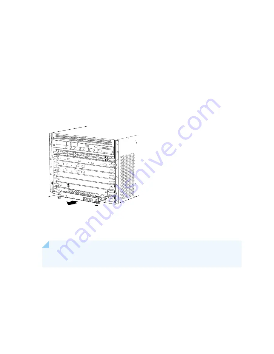
4. Flip the ejector handles outward to unseat the Routing Engine.
5. Grasp the Routing Engine by the ejector handles and slide it about halfway out of the chassis.
6. Place one hand underneath the Routing Engine to support it and slide it completely out of the chassis.
7. Place the Routing Engine on the antistatic mat.
Figure 123: Removing a Routing Engine
OK
MASTER
FAN
ONLINE
OFFLINE
0
1
1
0
FAIL
FAIL
PEM
FAIL
FAIL
FAIL
FAIL
FAIL
FAIL
ESD
OK
OK
OK
OK
OK
OK
OK
2
3
4
5
ACO/LT
YELLOW
ALARM
RED ALARM
NC
NO
C
NC
NO
C
REO
RE1
0 1 2 3
SCB
SCB
Routing
Engine
STATUS
SPU0
SERVICE
STATUS
SPU1
SERVICE
HA
OK/F
AIL
CHASSIS
CLUSTER
CONTROL 0
ENABLE
LINK/ACT
CHASSIS
CLUSTER
CONTROL 1
ENABLE
LINK/ACT
STATUS
SPU0
SERVICE
STATUS
SPU1
SERVICE
HA
OK/F
AIL
CHASSIS
CLUSTER
CONTROL 0
ENABLE
LINK/ACT
CHASSIS
CLUSTER
CONTROL 1
ENABLE
LINK/ACT
g030250
Installing the SRX5600 Services Gateway Routing Engine
To install a Routing Engine into an SCB (see
NOTE:
If you install only one Routing Engine in the service gateway, you must install it in SCB
slot 0 of service gateway chassis.
1. If you have not already done so, take the host subsystem offline. See
Gateway Host Subsystem Offline” on page 271
2. Wrap and fasten one end of the ESD grounding strap around your bare wrist, and connect the other
end of the strap to the ESD point on the chassis.
277
Содержание SRX5600
Страница 1: ...SRX5600 Services Gateway Hardware Guide Published 2020 02 14 ...
Страница 23: ......
Страница 105: ...LEDs 106 ...
Страница 114: ...Figure 51 SRX5K MPC g030309 MPC empty 115 ...
Страница 124: ...Port and Interface Numbering 125 ...
Страница 130: ...Port and Interface Numbering 131 ...
Страница 156: ......
Страница 183: ...Table 54 RJ 45 Connector Pinout for the AUX and CONSOLE Ports continued Description Signal Pin Clear to Send CTS 8 185 ...
Страница 185: ......
Страница 193: ...Figure 84 Installing the Front Mounting Hardware for a Four Post Rack or Cabinet 196 ...
Страница 239: ......
Страница 285: ...c Upload the configuration to RE2 from the USB device 288 ...
Страница 372: ...5 CHAPTER Troubleshooting Hardware Troubleshooting the SRX5600 377 ...
Страница 373: ......
Страница 407: ......
Страница 420: ...423 ...
Страница 423: ...Restricted Access Area Warning 426 ...
Страница 430: ...433 ...
Страница 443: ...Jewelry Removal Warning 446 ...
Страница 446: ...Operating Temperature Warning 449 ...
Страница 456: ...DC Power Disconnection Warning 459 ...
Страница 460: ...DC Power Wiring Sequence Warning 463 ...
Страница 463: ...DC Power Wiring Terminations Warning 466 ...
Страница 466: ...DC Power Disconnection Warning 469 ...
Страница 470: ...DC Power Wiring Sequence Warning 473 ...
Страница 473: ...DC Power Wiring Terminations Warning 476 ...


