


JOHNSON CONTROLS
205
SECTION 6 - TECHNICAL DATA
FORM 201.23-NM2
ISSUE DATE: 3/9/2015
6
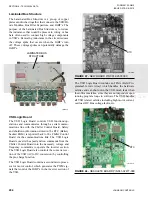
Inputs to the VSD Logic Board are fed through an
onboard multiplexer (MUX) before being sent to the
A/D converter. These signals allow the VSD Logic
Board to monitor DC Bus voltages, compressor mo-
tor currents, VSD internal ambient temperature, IGBT
baseplate temperatures, and compressor overload set-
tings.
The VSD Logic Board controls the glycol pump and
the cabinet cooling fans. Details on the controls are
provided in the
VSD Operation and Controls on page
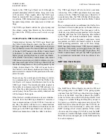
Control Panel to VSD Communications
Communication between the VSD Logic Board and
the Chiller Control Board is made via a three-wire RS-
485 opto-coupled data link. Communications between
the two boards occurs at the rate of 9600 baud. UART2
of the dual UART located on the Chiller Control Board
is dedicated to internal communications and has a
higher priority interrupt than the external communica-
tions UART1. The Chiller Control Board will control
VSD start/stop, selection of which compressors to run,
and compressor speed. The VSD Logic Board will run
the desired compressors at the speed requested by the
Chiller Control Board. The VSD will report back to
the Chiller Control Board, shutdown and safety infor-
mation related to internal VSD operation and the com-
pressor motors.
On power-up, the control panel will attempt to initial-
ize communications with the VSD. The Chiller Con-
trol Board will request initialization data from the
VSD Logic Board. The initialization data required is
the number of compressors and the VSD software ver-
sion. Once these data points have been received by the
control panel, the unit has successfully initialized and
will not request them again.
If the Chiller Control Board does not receive initializa-
tion data from the VSD Logic Board in 8 seconds or
loses communications with the VSD for 8 seconds at
any time, the chiller will fault on a communications
failure. The Chiller Control Board will continue to send
messages to the VSD Logic Board in an attempt to es-
tablish communications while the chiller is faulted.
The VSD Logic Board will also monitor a communi-
cations loss. If the VSD Logic Board loses communi-
cations with the Chiller Microprocessor Board for 8
seconds at any time, the VSD will shut off all compres-
sors and wait for valid comms from the Chiller Control
Board.
Once communications is established, the Chiller Con-
trol Board will send a data packet on the data link once
every second at 9600 baud. This data packet will in-
clude run, stop, and speed commands as well as request
operating data from the VSD. Operating data returned
by the VSD will include individual motor currents,
motor %FLA’s, output frequency, compressor motor
temperature, and fault information related to internal
VSD operating parameters such as DC Bus voltage,
IGBT baseplate temperatures, VSD internal ambient,
pre-charge relay status, power supply status, run relay
status, motor overload, and supply single phase. The
Chiller Control Board will poll the VSD Logic Board
for information continuously while the chiller is run-
ning.
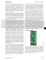
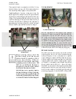
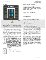
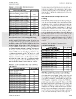
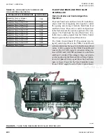
IGBT Gate Driver Boards
LD10613
The IGBT Gate Driver Boards provide the ON and
OFF gating pulses to the IGBT’s. The gating signals
originate from the VSD Logic Board and are changed
in level by the IGBT Gate Driver Board. The IGBT’s
in the inverter section of the VSD, change the DC Link
voltage to a variable Voltage and Frequency output to
the motor, to control the compressor motor speed. The
IGBT Gate Driver Boards also provides VCE SAT de-
tection (short circuit detection) to safely turn off the
IGBT’s during a short circuit condition. When a short
circuit occurs, the voltage (VCE SAT) across the IGBT
increases as a result of the high current. The IGBT Gate
Driver Board is an integral part of the IGBT assembly
for each compressor.
Содержание YCIV0157
Страница 18: ...JOHNSON CONTROLS 18 FORM 201 23 NM2 ISSUE DATE 3 9 2015 SAFETY SYMBOLS THIS PAGE INTENTIONALLY LEFT BLANK ...
Страница 38: ...JOHNSON CONTROLS 38 FORM 201 23 NM2 ISSUE DATE 3 9 2015 THIS PAGE INTENTIONALLY LEFT BLANK ...
Страница 42: ...JOHNSON CONTROLS 42 FORM 201 23 NM2 ISSUE DATE 3 9 2015 THIS PAGE INTENTIONALLY LEFT BLANK ...
Страница 50: ...JOHNSON CONTROLS 50 FORM 201 23 NM2 ISSUE DATE 3 9 2015 THIS PAGE INTENTIONALLY LEFT BLANK ...
Страница 104: ...JOHNSON CONTROLS 104 FORM 201 23 NM2 ISSUE DATE 3 9 2015 SECTION 6 TECHNICAL DATA Panel Layout 2 Compressor Models ...
Страница 105: ...JOHNSON CONTROLS 105 SECTION 6 TECHNICAL DATA FORM 201 23 NM2 ISSUE DATE 3 9 2015 THIS PAGE INTENTIONALLY LEFT BLANK ...
Страница 115: ...JOHNSON CONTROLS 115 SECTION 6 TECHNICAL DATA FORM 201 23 NM2 ISSUE DATE 3 9 2015 THIS PAGE INTENTIONALLY LEFT BLANK ...
Страница 119: ...JOHNSON CONTROLS 119 SECTION 6 TECHNICAL DATA FORM 201 23 NM2 ISSUE DATE 3 9 2015 THIS PAGE INTENTIONALLY LEFT BLANK ...
Страница 333: ...JOHNSON CONTROLS 333 FORM 201 23 NM2 ISSUE DATE 3 9 2015 NOTES ...


