


JOHNSON CONTROLS
265
SECTION 8 - MICROPANEL
FORM 201.23-NM2
ISSUE DATE: 3/9/2015
8
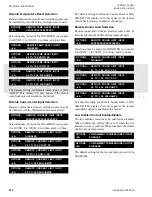
Chilled Liquid Setpoint Cooling Setpoints
SETPOINTS
LOCAL COOLING SETPOINT = XXX.X °F
This message displays the programmed cooling
setpoint at the time of the fault.
SETPOINTS
LOCAL CONTROL RANGE = +/- X.X °F
This message displays the programmed Control Range
at the time of the fault.
Remote Setpoint and Range
SETPOINTS REMOTE SETPOINT = XXX.X °F
REMOTE CONTROL RANGE = +/- X.X °F
This message displays the remote setpoint and Control
Range at the time of the fault.
Maximum Remote Temperature Setpoint
SETPOINTS
MAXIMUM REMOTE TEMP RESET = XXX.X °F
This message displays the maximum remote reset pro-
grammed at the time of the fault.
Options
Display Language
OPTIONS DISPLAY LANGUAGE
◄ ► XXXXXXXXXXXXXXXXXXXX
This message displays the language selected at the time
of the fault.
Chilled Liquid Cooling Mode
OPTIONS CHILLED LIQUID COOLING MODE
◄ ► WATER COOLING
This message displays the chilled liquid temperature
mode (water or glycol) selected at the time of the fault.
Local / Remote Control Mode
OPTIONS CHILLED LIQUID COOLING MODE
◄ ► GLYCOL COOLING
This message indicates whether Local or Remote Con-
trol Mode was selected at the time of the fault.
OPTIONS LOCAL / REMOTE CONTROL MODE
◄ ► XXXXXXXXXXXXXXXXXXXXX
When Remote Control Mode is selected, control of the
Chilled Liquid Setpoint is from a remote device such
as an ISN/BAS controller.
OPTIONS DISPLAY UNITS
◄ ► XXXXXXXXXXXXXXXXXXXX
Display Units Mode
This message indicates whether SI (°C, Barg) or Im-
perial units (°F, PSIG) was selected at the time of the
fault.
OPTIONS LEAD / LAG CONTROL MODE
◄ ► XXXXXXXXXXXXXXXXXXXXX
System Lead/Lag Control Mode
This message indicates the type of lead lag control se-
lected at the time of the fault. Five choices are avail-
able:
•
Automatic
•
Sys 1 Lead
•
Sys 2 Lead
•
Sys 3 Lead
•
Sys 4 Lead.
The default mode will be AUTOMATIC.
Remote Temperature Reset
One of the 5 messages below indicates whether remote
temperature reset was active or disabled at the chiller
keypad at the time of the fault. If active, the type of
reset signal selected is indicated. If the option is not
factory enabled, the option will not appear.
OPTIONS REMOTE TEMP RESET INPUT
◄ ►
DISABLED
OPTIONS REMOTE TEMP RESET INPUT
◄ ► 0.0 TO 10.0 VOLTS DC
OPTIONS REMOTE TEMP RESET INPUT
◄ ► 2.0 TO 10.0 VOLTS DC
OPTIONS REMOTE TEMP RESET INPUT
◄ ► 0.0 TO 20.0 MILLIAMPS
OPTIONS REMOTE TEMP RESET INPUT
◄ ► 4.0 TO 20.0 MILLIAMPS
Содержание YCIV0157
Страница 18: ...JOHNSON CONTROLS 18 FORM 201 23 NM2 ISSUE DATE 3 9 2015 SAFETY SYMBOLS THIS PAGE INTENTIONALLY LEFT BLANK ...
Страница 38: ...JOHNSON CONTROLS 38 FORM 201 23 NM2 ISSUE DATE 3 9 2015 THIS PAGE INTENTIONALLY LEFT BLANK ...
Страница 42: ...JOHNSON CONTROLS 42 FORM 201 23 NM2 ISSUE DATE 3 9 2015 THIS PAGE INTENTIONALLY LEFT BLANK ...
Страница 50: ...JOHNSON CONTROLS 50 FORM 201 23 NM2 ISSUE DATE 3 9 2015 THIS PAGE INTENTIONALLY LEFT BLANK ...
Страница 104: ...JOHNSON CONTROLS 104 FORM 201 23 NM2 ISSUE DATE 3 9 2015 SECTION 6 TECHNICAL DATA Panel Layout 2 Compressor Models ...
Страница 105: ...JOHNSON CONTROLS 105 SECTION 6 TECHNICAL DATA FORM 201 23 NM2 ISSUE DATE 3 9 2015 THIS PAGE INTENTIONALLY LEFT BLANK ...
Страница 115: ...JOHNSON CONTROLS 115 SECTION 6 TECHNICAL DATA FORM 201 23 NM2 ISSUE DATE 3 9 2015 THIS PAGE INTENTIONALLY LEFT BLANK ...
Страница 119: ...JOHNSON CONTROLS 119 SECTION 6 TECHNICAL DATA FORM 201 23 NM2 ISSUE DATE 3 9 2015 THIS PAGE INTENTIONALLY LEFT BLANK ...
Страница 333: ...JOHNSON CONTROLS 333 FORM 201 23 NM2 ISSUE DATE 3 9 2015 NOTES ...


