


JOHNSON CONTROLS
227
SECTION 7 - OPERATION
FORM 201.23-NM2
ISSUE DATE: 3/9/2015
7
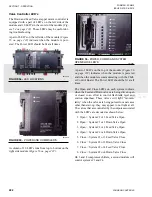
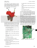
Control Board jumper JP4 must be positioned cor-
rectly to receive either a voltage (0 through 10VDC
or 2 through 10VDC) or current (0 through 20mA or
4 through 20mA) signal. Place the jumper in the “V”
position for a voltage signal or mA for a current signal
(See Figure 27 on page 178 and Figure 28 on page
The software must be configured under the OP-
TIONS key for the specific type of input signal to be
used.
The maximum temperature reset is achieved at ei-
ther 10VDC or 20mA. Sending the minimum signal
(0VDC, 2VDC, 0mA, or 4mA based on the OPTIONS
key setting) causes the setpoint to revert back to its lo-
cal programmed value. If the setpoint reset causes the
setpoint to go over the maximum programmable value,
it will be set to the maximum programmable setpoint.
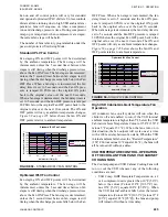
0 through 10VDC Reset Input
A 0VDC signal produces a 0°F reset. A 10VDC signal
produces the maximum remote temp reset (program-
mable under the SETPOINTS key). The setpoint reset
is ramped linearly between these limits as the input
varies between 0VDC and 10VDC. In order for this
input to work properly, the Remote Temperature Re-
set must be programmed for 0 through 10VDC input
(OPTIONS key) and Chiller Control Board jumper JP4
placed in the “V” position.
2 through 10VDC Reset Input
A 0 - 2VDC signal produces a 0°F reset. A 10VDC
signal produces the maximum remote temp reset (pro-
grammable under the SETPOINTS key). The setpoint
reset is ramped linearly between these limits as the
input varies between 2VDC and 10VDC. In order for
this input to work properly, the Remote Temperature
Reset must be programmed for 2 through 10VDC input
(OPTIONS key) and Chiller Control Board jumper JP4
placed in the “V” position.
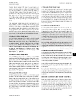
0 through 20mA Reset Input
A 0mA signal produces a 0°F reset. A 20mA signal
produces the maximum remote temp reset (program-
mable under the SETPOINTS key). The setpoint reset
is ramped linearly between these limits as the input
varies between 0mA and 20mA. In order for this input
to work properly, the Remote Temperature Reset must
be programmed for 0 through 20mA input (OPTIONS
key) and Chiller Control Board jumper JP4 placed in
the “mA” position.
4 through 20mA Reset Input
A 0 - 4mA signal produces a 0°F reset. A 20mA signal
produces the maximum remote temp reset (program-
mable under the SETPOINTS key). The setpoint reset
is ramped linearly between these limits as the input
varies between 4mA and 20mA. In order for this input
to work properly, the Remote Temperature Reset must
be programmed for 4 through 20mA input (OPTIONS
key) and Chiller Control Board jumper JP4 placed in
the “mA” position.
Local Current Limit Control
Local Current Limit Control is used to set the ac-
tual Current Limit Setpoint. This is accomplished by
changing the Local Current Limit Setpoint under the
PROGRAM key. This is the value at which the unit
will begin to current limit and override capacity control
if remote reset is not actively overriding this control. If
any other current limit methods are active, the lowest
value will be used.
Keep in mind that limiting current may interfere with
capacity control, pulling down chilled liquid tempera-
tures on hot water starts, and maintaining chilled liquid
setpoints.
Pulldown Current Limit Setpoint
The Pulldown Current Limit Setpoint can be set under
the PROGRAM key. This current limit setpoint is only
active on start-up for the time defined by the Pulldown
Current Limit Time under the PROGRAM key. After
the run time has exceeded this time, the Pulldown Cur-
rent Limit Setpoint is ignored.
This control is useful in limiting current pulldown de-
mand during peak usage periods where electric costs
are highest.
Keep in mind that limiting current may interfere with
capacity control, pulling down chilled liquid tempera-
tures on hot water starts, and maintaining chilled liquid
setpoints.
REMOTE CURRENT LIMIT RESET CONTROL
Remote Current Limit Reset is used to reset the actu-
al current limit setpoint used in current limit control.
There are several ways to change the current limit
setpoint. The first is by reprogramming the Local Cur-
rent Limit Setpoint under the PROGRAM key. This is
the value the unit will control the current limit to if
neither of the other methods is active.
Содержание YCIV0157
Страница 18: ...JOHNSON CONTROLS 18 FORM 201 23 NM2 ISSUE DATE 3 9 2015 SAFETY SYMBOLS THIS PAGE INTENTIONALLY LEFT BLANK ...
Страница 38: ...JOHNSON CONTROLS 38 FORM 201 23 NM2 ISSUE DATE 3 9 2015 THIS PAGE INTENTIONALLY LEFT BLANK ...
Страница 42: ...JOHNSON CONTROLS 42 FORM 201 23 NM2 ISSUE DATE 3 9 2015 THIS PAGE INTENTIONALLY LEFT BLANK ...
Страница 50: ...JOHNSON CONTROLS 50 FORM 201 23 NM2 ISSUE DATE 3 9 2015 THIS PAGE INTENTIONALLY LEFT BLANK ...
Страница 104: ...JOHNSON CONTROLS 104 FORM 201 23 NM2 ISSUE DATE 3 9 2015 SECTION 6 TECHNICAL DATA Panel Layout 2 Compressor Models ...
Страница 105: ...JOHNSON CONTROLS 105 SECTION 6 TECHNICAL DATA FORM 201 23 NM2 ISSUE DATE 3 9 2015 THIS PAGE INTENTIONALLY LEFT BLANK ...
Страница 115: ...JOHNSON CONTROLS 115 SECTION 6 TECHNICAL DATA FORM 201 23 NM2 ISSUE DATE 3 9 2015 THIS PAGE INTENTIONALLY LEFT BLANK ...
Страница 119: ...JOHNSON CONTROLS 119 SECTION 6 TECHNICAL DATA FORM 201 23 NM2 ISSUE DATE 3 9 2015 THIS PAGE INTENTIONALLY LEFT BLANK ...
Страница 333: ...JOHNSON CONTROLS 333 FORM 201 23 NM2 ISSUE DATE 3 9 2015 NOTES ...


