


JOHNSON CONTROLS
228
FORM 201.23-NM2
ISSUE DATE: 3/9/2015
SECTION 7 - OPERATION
Remote Current Limit Reset is only possible if the op-
tion is enabled by both the OPTIONS key selection and
in the factory programmable password protected Unit
Setup Mode.
Remote ISN Current Limit Setpoint
The ISN Current Limit Setpoint can be set via the ISN
comms. The control panel will only accept a Current
Limit Setpoint from the ISN if the control panel is in
Remote Control Mode (under the OPTIONS key). If
the control panel is in Local Control Mode, the ISN
setpoint will be ignored. The minimum and maximum
allowable values will be the same as the minimum and
maximum allowable reset values for the Current Limit
Setpoint under the PROGRAM key. If these values are
exceeded, the minimum or maximum value will be
used.
Contact a local Johnson Controls ISN Representative
for details on ISN controls and capabilities.
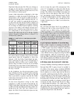
Remote Current Limit Reset
The Current Limit Setpoint can be set or reset via the
Remote Current Limit analog input. A zero signal in-
put (0% input) equates to the maximum current limit
setpoint as defined under the PROGRAM key Cur-
rent Limit Setpoint. A full scale signal input (100%
input) equates to the minimum current limit setpoint
as defined under the PROGRAM key Current Limit
Setpoint. The current limit value is linear and may be
adjusted anywhere between the maximum and mini-
mum points of 0 (no offset) and 100% (max. current
limiting).
This input may be used either in Local or Remote Con-
trol Mode. This input will be ignored if the Remote
Current Limit is disabled under the OPTIONS key.
Once a change to the input is registered, a timer is set
to the value of the Remote Inputs Service Time as pro-
grammable under the Unit Setup Mode at the factory
for the default value of 15 minutes. The low limit is 5
minutes and the high limit is 60 minutes. The Remote
input will be ignored until this timer expires. The tim-
er assures that rapid changes in a remote reset signal
don’t result in poor temperature control or excessive
compressor cycling. In most instances, this timer will
not need to be changed, since reset more often than 15
minutes will create problems with chilled liquid tem-
perature control. Factory Service should be contacted
if a timer change is required.
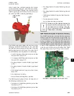
Control board jumper JP5 must be positioned correctly
to receive either a voltage (0 to 10VDC or 2 to 10VDC)
or current (0 to 20mA or 4 to 20mA) signal. Place the
jumper in the “V” position for a voltage signal or mA
for a current signal
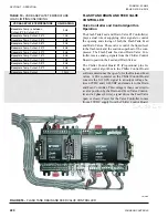
(See Figure 27 on page 178 and
. The software must be con-
figured under the OPTIONS key for the type of input
signal to be used.
The minimum current limit setpoint is achieved at ei-
ther 10VDC or 20mA. Sending the minimum signal
(0VDC, 2VDC, 0mA, or 4mA based on the OPTIONS
key setting) causes the current limit to revert back to its
maximum value.
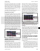
0 through Reset Input
A 0VDC signal sets the current limit to the maximum
value. A 10VDC signal sets the current limit to the
minimum value. The current limit is ramped linearly
between these limits as the input varies between 0VDC
and 10VDC. In order for this input to work properly,
the Remote Current Limit must be programmed for
0 through 10VDC input (OPTIONS key) and Chiller
Control Board jumper JP5 placed in the “V” position.
2 through 10VDC Reset Input
A 0 - 2VDC signal sets the current limit to the maxi-
mum value. A 10VDC signal sets the current limit to the
minimum value. The current limit is ramped linearly
between these limits as the input varies between 2VDC
and 10VDC. In order for this input to work properly,
the Remote Current Limit must be programmed for
2 through 10VDC input (OPTIONS key) and Chiller
Control Board jumper JP5 placed in the “V” position.
0 through 20mA Reset Input
A 0mA signal sets the current limit to the maximum
value. A 20mA signal sets the current limit to the mini-
mum value. The current limit is ramped linearly be-
tween these limits as the input varies between 0mA
and 20mA. In order for this input to work properly,
the Remote Current Limit must be programmed for 0
through 20mA input (OPTIONS key) and Chiller Con-
trol Board jumper JP5 placed in the “mA” position.
4 through 20mA Reset Input
A 4mA signal sets the current limit to the maximum
value. A 20mA signal sets the current limit to the mini-
mum value. The current limit is ramped linearly be-
tween these limits as the input varies between 4mA
and 20mA. In order for this input to work properly,
the Remote Current Limit must be programmed for 4
through 20mA input (OPTIONS key) and Chiller Con-
trol Board jumper JP5 placed in the “mA” position.
Содержание YCIV0157
Страница 18: ...JOHNSON CONTROLS 18 FORM 201 23 NM2 ISSUE DATE 3 9 2015 SAFETY SYMBOLS THIS PAGE INTENTIONALLY LEFT BLANK ...
Страница 38: ...JOHNSON CONTROLS 38 FORM 201 23 NM2 ISSUE DATE 3 9 2015 THIS PAGE INTENTIONALLY LEFT BLANK ...
Страница 42: ...JOHNSON CONTROLS 42 FORM 201 23 NM2 ISSUE DATE 3 9 2015 THIS PAGE INTENTIONALLY LEFT BLANK ...
Страница 50: ...JOHNSON CONTROLS 50 FORM 201 23 NM2 ISSUE DATE 3 9 2015 THIS PAGE INTENTIONALLY LEFT BLANK ...
Страница 104: ...JOHNSON CONTROLS 104 FORM 201 23 NM2 ISSUE DATE 3 9 2015 SECTION 6 TECHNICAL DATA Panel Layout 2 Compressor Models ...
Страница 105: ...JOHNSON CONTROLS 105 SECTION 6 TECHNICAL DATA FORM 201 23 NM2 ISSUE DATE 3 9 2015 THIS PAGE INTENTIONALLY LEFT BLANK ...
Страница 115: ...JOHNSON CONTROLS 115 SECTION 6 TECHNICAL DATA FORM 201 23 NM2 ISSUE DATE 3 9 2015 THIS PAGE INTENTIONALLY LEFT BLANK ...
Страница 119: ...JOHNSON CONTROLS 119 SECTION 6 TECHNICAL DATA FORM 201 23 NM2 ISSUE DATE 3 9 2015 THIS PAGE INTENTIONALLY LEFT BLANK ...
Страница 333: ...JOHNSON CONTROLS 333 FORM 201 23 NM2 ISSUE DATE 3 9 2015 NOTES ...


