


JOHNSON CONTROLS
284
FORM 201.23-NM2
ISSUE DATE: 3/9/2015
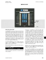
SECTION 8 - MICROPANEL
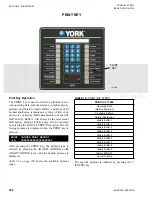
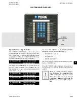
The data sections are listed below:
•
Software Versions
•
Analog Inputs
•
Digital Inputs
•
Digital Outputs
•
Analog Outputs
•
VSD Logic Digital Output
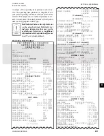
SERVICE SOFTWARE VERSIONS
CONTROL = C.AXX.ZZ.YY VSD = C.VXX.ZZ.YY
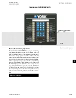
The software version of the chiller Micro Control
Board and the VSD microprocessor are viewable in the
first data section.
XX, YY, and ZZ will be filled in with alphanumeric
characters.
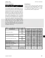
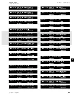
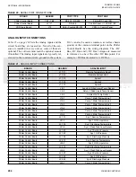
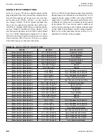
The second data section displays the Analog Inputs
(AI). Displays for 3 and 4 compressor chillers are
skipped if the unit does not have those systems. These
messages will only be displayed in English. The volt-
age displayed is referenced to common (return, ground)
in the system. J12-3 can also be used as common, as
well as chassis ground, or the common terminal point
on the Chiller Control Board.
See the wiring diagrams.
SERVICE AI J17-11 REMOTE TEMP RESET
X.X VDC
= XXX.X %
SERVICE AI J17-12 REMOTE CURRENT LIMIT
X.X VDC
= XXX.X %
SERVICE AI J17-13 REMOTE SOUND LIMIT
X.X VDC
= XXX.X %
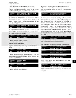
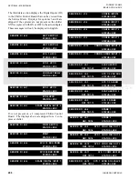
The Remote Temp Reset, Remote Current Limit Reset,
and Remote Sound Limit inputs have onboard voltage
dividers, if the jumper is set for a voltage input. This
will cause the voltage read on the display to be less
than the voltage on the board header inputs between
TB1-17 and 18, TB1-19 and 20, or TB1-40 and 41). To
correct for this when measuring voltage at the remote
device supplying voltage to the board header while
troubleshooting, use the following calculation:
Voltage = 10 x VDC volts / 4.5
If the input is programmed for a current input, the volt-
age read by the MUX is displayed. If the input is dis-
abled under the OPTIONS key, the voltage display will
display “DISABLED”.
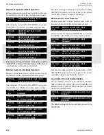
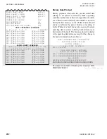
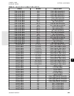
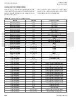
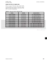
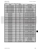
The analog inputs display will continue to sequence as
follows. The inputs indicate voltages read between the
input terminal to the Chiller Logic Board and the plug
GND or Drain.
SERVICE AI J17-14 SPARE ANALOG 1
X.X VDC
SERVICE AI J17-15 SPARE ANALOG 2
X.X VDC
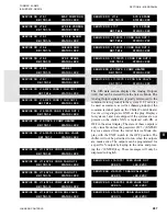
SERVICE AI J18-7 LEAVING LIQUID TEMP
X.X VDC
= XXX.X °F
SERVICE AI J18-8 RETURN LIQUID TEMP
X.X VDC
= XXX.X °F
SERVICE AI J18-9 AMBIENT AIR TEMP
X.X VDC
= XXX.X °F
SERVICE AI J19-1 SYS1 MOTOR TEMP T1
X.X VDC
= XXX.X °F
SERVICE AI J19-2 SYS1 MOTOR TEMP T2
X.X VDC
= XXX.X °F
SERVICE AI J19-3 SYS1 MOTOR TEMP T3
X.X VDC
= XXX.X °F
SERVICE AI J19-6 SYS2 MOTOR TEMP T1
X.X VDC
= XXX.X °F
SERVICE AI J19-7 SYS2 MOTOR TEMP T2
X.X VDC
= XXX.X °F
SERVICE AI J19-8 SYS2 MOTOR TEMP T3
X.X VDC
= XXX.X °F
SERVICE AI J20-1 SYS3 MOTOR TEMP T1
X.X VDC
= XXX.X °F
SERVICE AI J20-2 SYS3 MOTOR TEMP T2
X.X VDC
= XXX.X °F
Содержание YCIV0157
Страница 18: ...JOHNSON CONTROLS 18 FORM 201 23 NM2 ISSUE DATE 3 9 2015 SAFETY SYMBOLS THIS PAGE INTENTIONALLY LEFT BLANK ...
Страница 38: ...JOHNSON CONTROLS 38 FORM 201 23 NM2 ISSUE DATE 3 9 2015 THIS PAGE INTENTIONALLY LEFT BLANK ...
Страница 42: ...JOHNSON CONTROLS 42 FORM 201 23 NM2 ISSUE DATE 3 9 2015 THIS PAGE INTENTIONALLY LEFT BLANK ...
Страница 50: ...JOHNSON CONTROLS 50 FORM 201 23 NM2 ISSUE DATE 3 9 2015 THIS PAGE INTENTIONALLY LEFT BLANK ...
Страница 104: ...JOHNSON CONTROLS 104 FORM 201 23 NM2 ISSUE DATE 3 9 2015 SECTION 6 TECHNICAL DATA Panel Layout 2 Compressor Models ...
Страница 105: ...JOHNSON CONTROLS 105 SECTION 6 TECHNICAL DATA FORM 201 23 NM2 ISSUE DATE 3 9 2015 THIS PAGE INTENTIONALLY LEFT BLANK ...
Страница 115: ...JOHNSON CONTROLS 115 SECTION 6 TECHNICAL DATA FORM 201 23 NM2 ISSUE DATE 3 9 2015 THIS PAGE INTENTIONALLY LEFT BLANK ...
Страница 119: ...JOHNSON CONTROLS 119 SECTION 6 TECHNICAL DATA FORM 201 23 NM2 ISSUE DATE 3 9 2015 THIS PAGE INTENTIONALLY LEFT BLANK ...
Страница 333: ...JOHNSON CONTROLS 333 FORM 201 23 NM2 ISSUE DATE 3 9 2015 NOTES ...


