Installing the VIS
11
VISCAM 1000 Systems
3.2.2
X6 Power Input Connector
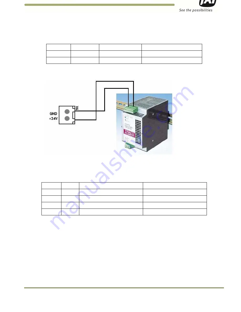
The Power Input connection to the J-Panel is shown in Table 3 and Figure 12. Note: X7 is in parallel to X6.
Table 3
Power input to the J-Panel
X6 Pin #
Signal
Description
Connection to
1
+24V
+24V dc
24V DC power output
2
GND
+24V return
24V DC power supply return
Figure 12.
X-6 Power input connection
3.2.3
Trigger Input Connector (X14)
The Trigger input connection to the J-Panel is connector X14. The connections are listed in Table 4 and
Figure 13.
Table 4
Trigger input connector.
X14 Pin # Signal
Description
Connection to
1
Trig0+
Positive Trigger input to camera 0
Trigger device positive terminal
2
Trig0-
Negative Trigger input to camera 0
Trigger device negative terminal
3
Trig1+
Positive Trigger input to camera 1
Trigger device positive terminal
4
Trig1-
Negative Trigger input to camera 1
Trigger device negative terminal
3.2.5 (a) Trigger polarity
The switches S3 and S5 set the trigger polarity:
If the trigger signal is normally low (no voltage at trigger input) the switch shall be in position:
Arrow up - positive going
If the trigger signal is normally high (voltage at trigger input) the switch shall be in position:
Arrow down – negative going
As a guideline the two LEDs marked TRIG-0 and TRIG-1 on the VJP-300 J-Panel shall be off when no trigger
pulse is present.
Содержание VISCAM 1000 System
Страница 1: ...VISCAM 1000 System Vehicle Imaging Subsystem Document P N 10873 Document Version C...
Страница 2: ......


