VIS-CAM Systems
42
System Set-Up
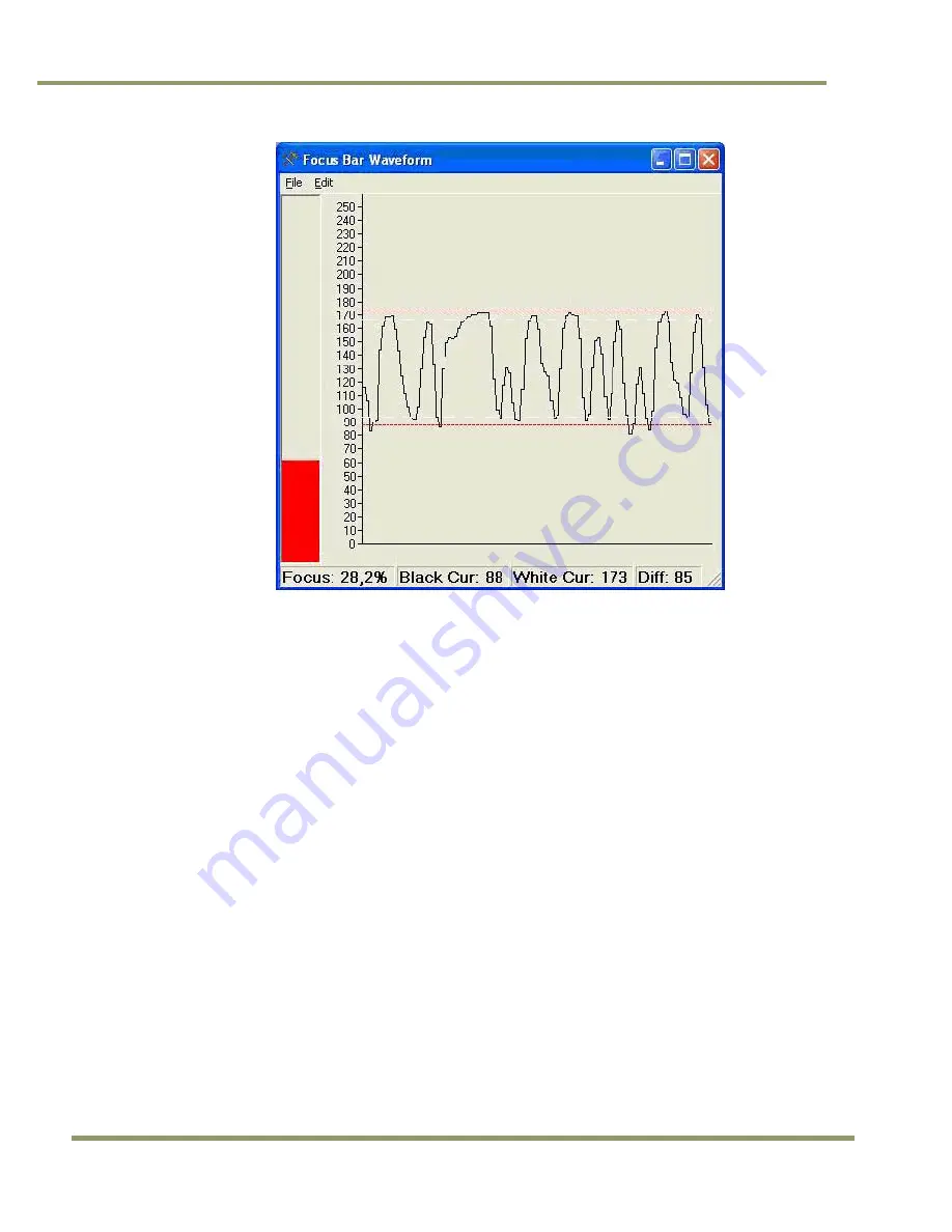
Figure 42.
Focus Bar Waveform Display with waveform cursors.
9. Use one hand to carefully hold the focus ring of the lens in place while you rotate the filter ring
on the very front of the lens with your other hand. Turn the filter ring until the white mark on
the ring is oriented straight up (or down). Secure the filter ring in place with a small dab of RTV
glue.
10. Printout the image of the screen using the “File -> Print…” menus on both the “Video Window”
and the “Focus Bar Waveform” windows to document the settings. If no printers are connected,
the “PDFCreator” printer driver can be used to save the pictures as PDF-files.
11. Have your assistant move the plate stand back to the near trigger line and re-position the plate
at the minimum plate height.
12. Drive the setup vehicle slowly towards the trigger line in the same heading as normal traffic
flow and center it directly between the camera being aligned and the adjacent camera that has
already been aligned. Marking the position halfway between adjacent cameras at the trigger
line with some marker is advisable to help the driver properly aim the vehicle.
13. Park the vehicle at the location where it just barely causes the trigger to cause an image to be
captured. For loop triggers, park the vehicle where a vehicle would normally be located when
the loop trigger signals the VIS to capture an image.
4.1.11
Flash Head Alignment
The following section provides a general procedure to align the VIS flash head. Be sure to follow any specific
alignment procedure provided with your system.
Align the flash head at night and after aligning the cameras. Park a light colored vehicle underneath the
camera and where the vehicle detector triggers the camera.
Содержание VIS-CAM System
Страница 1: ...VIS CAM System Vehicle Imaging Subsystem Document Version 10436 Document P N E...
Страница 2: ......
Страница 12: ...VIS CAM Systems xii List of Tables...
Страница 20: ...VIS CAM Systems 8 Preparing for Installation Figure 5 VIS 300 U S Camera options chart...
Страница 21: ...Preparing for Installation 9 VIS CAM Systems Figure 6 VIS 350 U S Camera options chart...
Страница 22: ...VIS CAM Systems 10 Preparing for Installation Figure 7 VIS 400 U S Camera options chart...
Страница 23: ...Preparing for Installation 11 VIS CAM Systems Figure 8 VIS 500 U S Camera options chart...
Страница 24: ...VIS CAM Systems 12 Preparing for Installation Figure 9 VIS 300 European Camera options chart...
Страница 25: ...Preparing for Installation 13 VIS CAM Systems Figure 10 VIS 350 European Camera options chart...
Страница 26: ...VIS CAM Systems 14 Preparing for Installation Figure 11 VIS 400 European Camera options chart...
Страница 27: ...Preparing for Installation 15 VIS CAM Systems Figure 12 VIS 500 European Camera options chart...
Страница 92: ...VIS CAM Systems 80 Appendix B Figure 90 Lane controller setup...
Страница 100: ...VIS CAM Systems 88 Appendix E Figure 98 Operation configuration of Serial port 1...
Страница 110: ......
Страница 111: ......


