VIS-CAM Systems
90
Appendix F
10
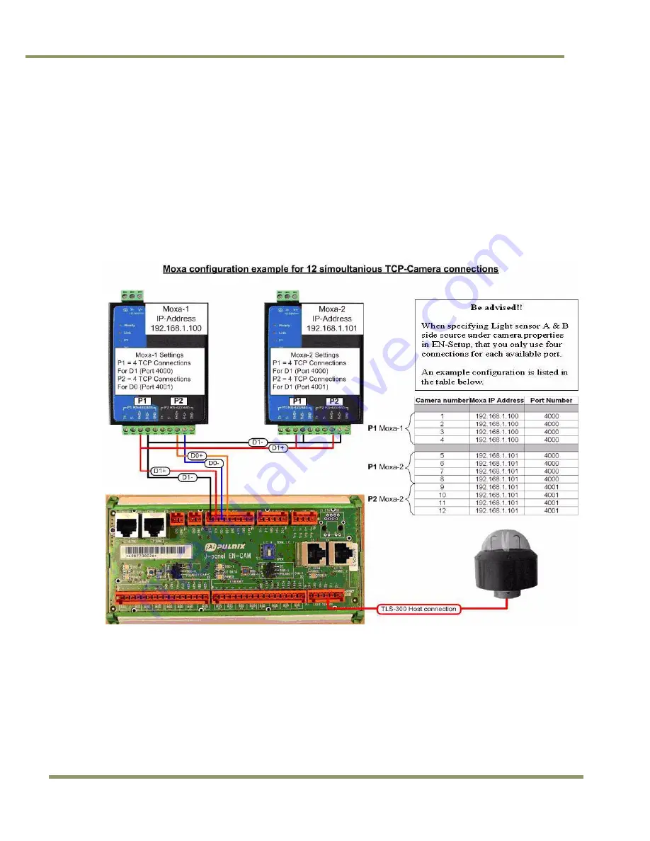
Appendix F: Multiple Moxa N-port Configuration Diagram
One Moxa N-port Device Server is capable of accommodating a maximum of four concurrent connections on
port 1. (Port 2 is reserved for control). Whenever more than four cameras are pointed to one Light Sensor, it is
necessary to connect multiple Moxa N-ports in parallel to support the number of cameras being deployed. The
second Moxa is capable of eight concurrent connections (four on each port).
Figure 101.Moxa configuration example.
*) 120 Ω termination resistors are mounted across R+ and R- on Moxa-2 (see Section 3.3.4)
Содержание VIS-CAM System
Страница 1: ...VIS CAM System Vehicle Imaging Subsystem Document Version 10436 Document P N E...
Страница 2: ......
Страница 12: ...VIS CAM Systems xii List of Tables...
Страница 20: ...VIS CAM Systems 8 Preparing for Installation Figure 5 VIS 300 U S Camera options chart...
Страница 21: ...Preparing for Installation 9 VIS CAM Systems Figure 6 VIS 350 U S Camera options chart...
Страница 22: ...VIS CAM Systems 10 Preparing for Installation Figure 7 VIS 400 U S Camera options chart...
Страница 23: ...Preparing for Installation 11 VIS CAM Systems Figure 8 VIS 500 U S Camera options chart...
Страница 24: ...VIS CAM Systems 12 Preparing for Installation Figure 9 VIS 300 European Camera options chart...
Страница 25: ...Preparing for Installation 13 VIS CAM Systems Figure 10 VIS 350 European Camera options chart...
Страница 26: ...VIS CAM Systems 14 Preparing for Installation Figure 11 VIS 400 European Camera options chart...
Страница 27: ...Preparing for Installation 15 VIS CAM Systems Figure 12 VIS 500 European Camera options chart...
Страница 92: ...VIS CAM Systems 80 Appendix B Figure 90 Lane controller setup...
Страница 100: ...VIS CAM Systems 88 Appendix E Figure 98 Operation configuration of Serial port 1...
Страница 110: ......
Страница 111: ......


