VIS-CAM Systems
84
Appendix E
9
Appendix E: Moxa N-Port 5232 Configuration
Configuration of the Moxa N-Port server is done through a standard web-browser or using Telnet.
If you are unfamiliar with the configuration terms, please consult the enclosed Moxa N-Port server manual.
To carry out the configuration using Internet Explorer, type the IP-address of the unit in the address field:
http://192.168.127.254 <CR>
You should now be able to configure the unit through the embedded web-server.
To carry out the configuration using Telnet, open the command prompt window – type the following: Telnet
192.168.127.254 <CR>
You should now be able to configure the unit through the Telnet interface.
The necessary settings will be listed under its designated sub-menu. The items underlined in bold italics
(example - Delimiter:
D
) must be configured as described.
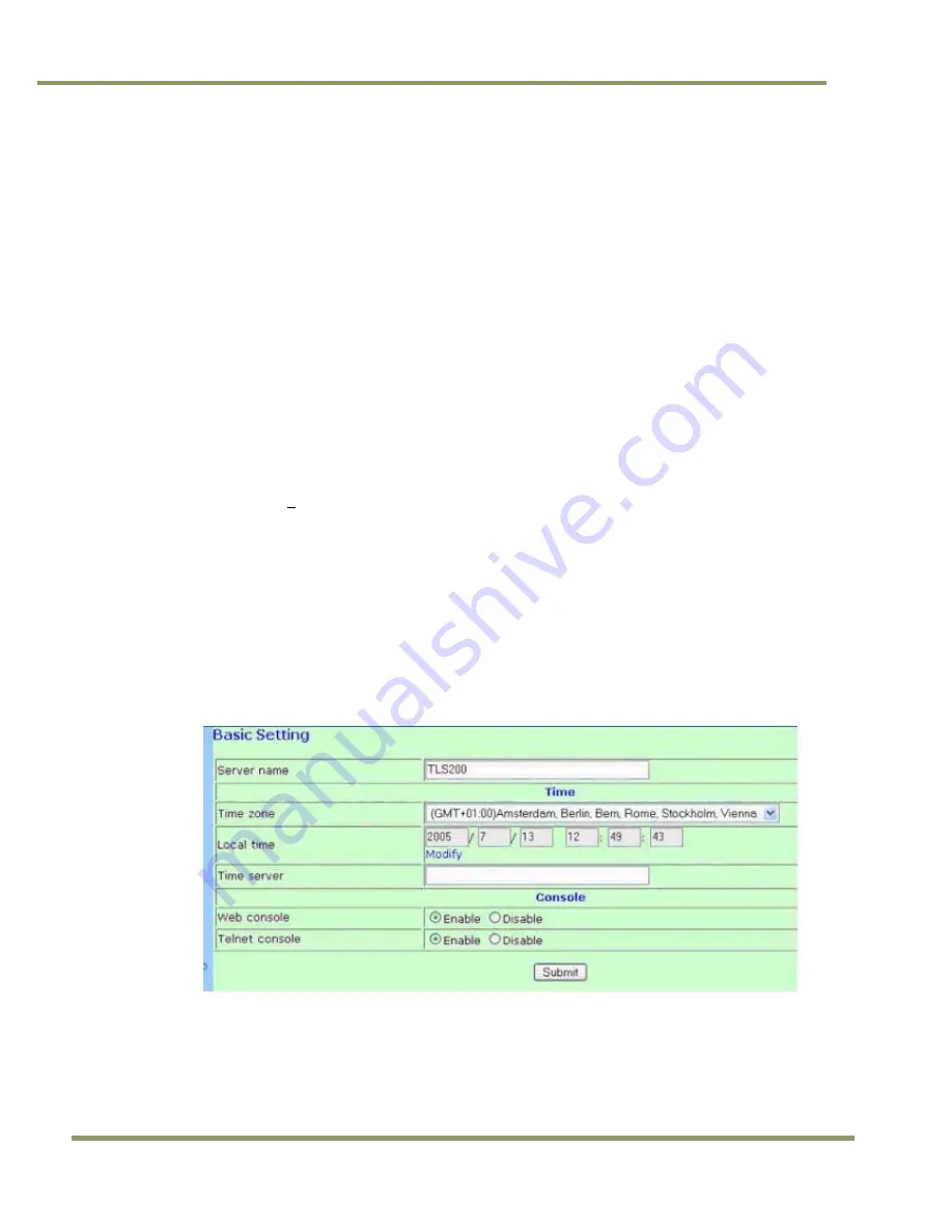
Basic Settings:
Server name:Enter the desired name for the N-Port server.
Time zone:Enter the correct time zone for the system location.
Local time:Enter the correct time for the system location.
Time server: Enter IP-Address or domain name for the desired time server.
Web console:Enables / Disables the web configuration utility.
Telnet console:Enables / Disables the Telnet configuration utility.
Figure 93.
Standard configuration of Basic Settings:
Network Settings:
IP address:Enter the desired IP address of the unit. The default address from the factory is 192.168.127.254
unless otherwise specified.
Netmask:Enter the subnet mask of the unit. The default subnet mask from the factory is 255.255.255.0 unless
otherwise specified.
Содержание VIS-CAM System
Страница 1: ...VIS CAM System Vehicle Imaging Subsystem Document Version 10436 Document P N E...
Страница 2: ......
Страница 12: ...VIS CAM Systems xii List of Tables...
Страница 20: ...VIS CAM Systems 8 Preparing for Installation Figure 5 VIS 300 U S Camera options chart...
Страница 21: ...Preparing for Installation 9 VIS CAM Systems Figure 6 VIS 350 U S Camera options chart...
Страница 22: ...VIS CAM Systems 10 Preparing for Installation Figure 7 VIS 400 U S Camera options chart...
Страница 23: ...Preparing for Installation 11 VIS CAM Systems Figure 8 VIS 500 U S Camera options chart...
Страница 24: ...VIS CAM Systems 12 Preparing for Installation Figure 9 VIS 300 European Camera options chart...
Страница 25: ...Preparing for Installation 13 VIS CAM Systems Figure 10 VIS 350 European Camera options chart...
Страница 26: ...VIS CAM Systems 14 Preparing for Installation Figure 11 VIS 400 European Camera options chart...
Страница 27: ...Preparing for Installation 15 VIS CAM Systems Figure 12 VIS 500 European Camera options chart...
Страница 92: ...VIS CAM Systems 80 Appendix B Figure 90 Lane controller setup...
Страница 100: ...VIS CAM Systems 88 Appendix E Figure 98 Operation configuration of Serial port 1...
Страница 110: ......
Страница 111: ......


