installation directiVe
22
MAY 2006
N40 ENT M25
N60 ENT M37-M40
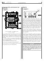
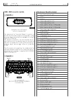
Connections of the central electronic unit
(ECU) EDC 7
A. 36 pole connector - A1. 16 pole connector -
A2. EDC at 89 poles.
The connection of the central electronic unit, ECU, to the
components of the EDC system is achieved by means of
three connectors to subdivide the wiring harnesses, thereby
favoring a quicker identification of the lines during testing
operations.
The different connectors are polarized and provided with
levers to favor the connection and disconnection operations
and assure proper coupling.
They are dedicated to the following functions:
o
Connector A for engine mounted components
o
Connector A1 reserved for electro-injector connection
o
Connector A2 for boat side connections
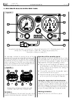
Relay box
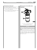
This shall be installed and anchored in such a way as to
dampen the vibrations and stresses occurring when under-
way, and they shall be accessible during servicing operations
and when underway. The electrical commands positioned on
the panel allow to control engine starting and stopping (2)
directly from the engine room, while excluding any possibil-
ity that anyone may involuntarily start the engine from the
bridge (1), during servicing operations. Among the controls
present on the panel are also the push-button (3) and the
“blink code” light indicator (4), useful to obtain, also while
underway, indications that will lead to identify failures or
improper engine operating conditions (see Chapter 20).
On the relay box is located the multipolar connector, pro-
tected by a screw-on lid (5), for connection with the com-
puterized diagnostic tools prescribed by IVECO MOTORS
(see Chapter 20).
Inside the box, anchored to a printed circuit board, are
present the power management relays of some components
and the elements that protect the electrical lines against
short circuits or excessive current absorption. These com-
ponents perform a similar function to that of fuses, almost
totally avoiding the need to restore the electrical continuity
of circuits subjected to an anomaly condition. These compo-
nents are able to limit and eliminate short circuit currents
without melting, restoring their own and the circuit’s electri-
cal continuity, once the cause of the anomaly is removed.
CAUTION
during the year 2005, some modifications were made to
the internal circuits of the relay box and to the wiring.
these modifications make incompatible and harmful the
use of the components supplied now together with the
components supplied before. please refer to the instruc-
tion shown in chapter 8.
Figure 16
04_060_N
A
A1
A2
5
3
2
1
4
04_074_N
Figure 1
Содержание NEF N40-ENT-M25
Страница 64: ...INSTALLATIONDIRECTIVE 64 N40 ENT M25 N60 ENT M37 M40 MAY 2006 ...
Страница 69: ......


