installation directiVe
0
N40 ENT M25
N60 ENT M37-M40
MAY 2006
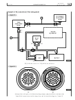
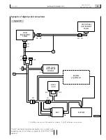
Installing the panel provided with digital displays requires con-
necting the JH connector of the panel to the JE connector of
the interface wire harness, itself connected to the “Converter
Module”, interposing the JE-JH extension wire harness, avail-
able in 3, 5 and 7 meter-long versions (Figure 24).
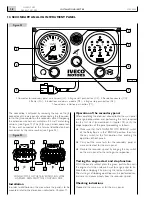
To the main panel is connected the JE connector, set for
connection to the secondary panel; in installations lacking the
secondary panel, do not remove the cap of the JE connector
in order not to compromise the electrical continuity of the
system power supply circuit.
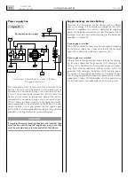
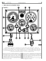
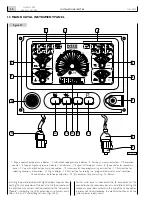
Figure 2
1. Engine coolant temperature indicator - 2. Lubrication loop pressure indicator - 3. Service and alarm indicators - 4. Revolution
counter - 5. Supercharger air pressure indicator - 6. Voltmeter - 7. Engine start/stop key switch - 8. JE connector for secondary
panel - 9. Cap with electrical continuity connection - 10. Accessory function programming push-button - 11. Push-button for
selecting accessory information - 12. Digital display - 13. Push-button for zeroing the “programmed maintenance” indication -
14. Sound alarm inhibition push-button - 15. JH connector for panel wiring - 16.-Buzzer.
RPM
X100
C
40
50
0
120
5
90
BAR
10
10
2
+
–
8
15
20
h
RPM
– +
V
35
MIN
30
0
MAX
BAR
3
25
1
2
ROG.
P
1
15
16
2
5
6
7
8
3
3
4
04_256_N
9
14
13
12
11
10
12. MAIN DIGITAL INSTRUMENT PANEL
Содержание NEF N40-ENT-M25
Страница 64: ...INSTALLATIONDIRECTIVE 64 N40 ENT M25 N60 ENT M37 M40 MAY 2006 ...
Страница 69: ......


