installation directiVe
4
MAY 2006
N40 ENT M25
N60 ENT M37-M40
Installation
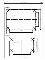
In order to drill holes on the area where the panel is to be
mounted, refer to the dimensions indicated in Chapter 14.
Operation of the panel
After completing the electrical connections and engine
preparation, perform the tests required for the first start, as
described in Chapter 18.
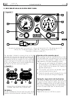
Verify the proper operation of the panel, proceeding as fol-
lows:
o
Make sure that the “ENGINE ROOM / BRIDGE” switch
of the Relay Box is in the “BRIDGE” position, then turn
the key switch to the first position and verify that the
instruments are powered and the indications and alarms
module runs the alarm test for about 5 seconds. During
this phase, all indicator lights must be lighted, with the
exception of those for “pre-lubrication”, “pre-post heat-
ing” and “EDC failure”. A sound signal must be emitted
by the buzzer; it may be silenced before the end of the
test, pressing the push-button on the panel.
o
Once the test is complete, only the indications pre-
scribed for the engine stopped must remain lighted: e.g.
“alternator charge” and “low oil pressure”; the analog
instruments must provide values consistent with the
respective physical parameters.
Testing the engine start function
Turn the key switch to the second position and keep it in it
until the engine has started, then release the switch, which
will stably return to the first position; after releasing the key,
the switch may be brought back to the starting position only
after the switch is returned to the resting or zero position.
Checking indications
After starting the engine, verify whether the operating
modes of the indications and alarms module are similar to
those set out above.
Using appropriate measuring instruments, verify the consist-
ency of the indications provided by the analog instruments.
Testing the engine stop function
The engine is stopped and the panel is disabled by returning
the key switch to the resting or zero position.
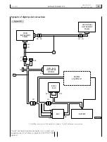
Check that the ECF and ECM connectors (present on the
wiring of the new model) are disconnected; the digital board
is not equipped with the engine stopping button and con-
sequently it would not be possible to stop the engine with
the key commuter with the activation of the engine stop if
stressed function.
Programming accessory functions
The following programming operations are required when
the panel is first operated:
o
The hours of the maintenance interval relevant to the
characteristics of the engine in use.
o
The maximum quantity of introduction, necessary to
compute fuel consumption.
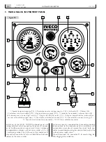
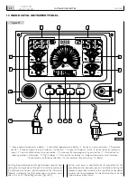
With reference to Figure 27, proceed as follows:
o
Holding down the “Programming” (10) and “Slide-down
selection” (11) push-buttons, positioned on the panel,
turn the key switch to the first position and wait for the
display to show the value of the maintenance interval
set previously (e.g., 200 hours).
o
Release the push-buttons and set the hours of the
time interval, indicated for oil replacement, provided on
the operation and maintenance manual; the operation
is completed by repeatedly pressing the “Slide-down
Selection” push-button (11) until the number that is
selected and highlighted by flashing is correctly set, then
operating the “Programming” push-button (10) to select
the number to set.
o
Press and hold the “Programming” push-button (10)
until the display shows the maximum introduction value,
set by default to the value 10 mg/strk, then release it.
o
Set the number for engine calibration, obtaining it from
the table that follows, proceeding as described in item
2.
o
Press and hold the “Programming” push-button (10)
until the display shows the engine rpm indication.
If programming operations were not performed correctly,
the display will show the indication “Err.P”; check whether
the electrical connections of the main panel and of the
converter module were performed correctly, then repeat
the procedure.
n40 ent m25
maximum power calibration
introduction
hp
mg/strk
250
128
200
108
170
95
Содержание NEF N40-ENT-M25
Страница 64: ...INSTALLATIONDIRECTIVE 64 N40 ENT M25 N60 ENT M37 M40 MAY 2006 ...
Страница 69: ......

