installation directiVe
20
MAY 2006
N40 ENT M25
N60 ENT M37-M40
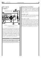
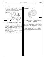
Power supply line
1.Alternator - 2. Electric starter motor - 3. Battery -
4. Engine wire harness.
The connection of the +B terminal of the alternator to the
po30 terminal of the electric starter motor must be
achieved with a conductor having a cross section of at least
10 mm
2
. The connection of the po30 terminal of the
electric starter motor to the positive pole of the battery,
achieved with a conductor having a cross section of at least
70 mm
2
, allows to obtain, as shown in the figure, the simulta-
neous connection of the alternator to the battery. The con-
nection between the engine ground and the negative pole
of the battery must be achieved according to the guidelines
provided in the Engine electrical ground paragraph.
CAUTION
if magneto-thermal protecting breakers are inserted, they
must not be used to stop the engine and in any case they
must be activated only a few seconds after shut-down.
Supplementary services battery
To assure that the engine can be started with a sufficient
quantity of energy, it is advisable to provide for the instal-
lation of a supplementary battery, dedicated to supplying
power to the on-board electrical services. The power line to
recharge it may be constructed according to the indications
provided in Chapter 24.
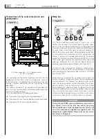
if one engine is installed
The battery used for services may be recharged interposing
on the power supply line a relay actuated by the recharge
signal of the alternator’s electronic regulator (D+).
if two engines are installed
The presence of two generators allows to keep the recharg-
ing functions separated: the generator (G1) recharges the
battery (AC1) dedicated to starting both engines and pow-
ering both electrical/electronic control circuits, whilst the
generator (G2) recharges the battery (AC2) used to power
the services. In two-engine applications, it is essential to con-
nect the engine grounds to a common potential; the solution
proposed in Chapter 24 fully complies with this need, assuring
the full functionality and independence of the two circuits.
M
50
D+
+B
30
05_004_N
4
1
2
3
Figure 1
equipment power supply
Содержание NEF N40-ENT-M25
Страница 64: ...INSTALLATIONDIRECTIVE 64 N40 ENT M25 N60 ENT M37 M40 MAY 2006 ...
Страница 69: ......


