installation directiVe
42
MAY 2006
N40 ENT M25
N60 ENT M37-M40
17. PREPARING THE ENGINE
FOR FIRST START-UP
1. Drain the residual 30/M protective oil from the sump.
2. Pour into the lubricating loop only lubricating oil of the
type and in the quantities set out in the Refilling Table.
3. Drain the CFB protective liquid from the fuel loop,
completing the operations as indicated under item 3. of
Chapter 23.
4. Remove the caps and/or seals from the engine intake,
exhaust, aeration and venting ports, restoring normal
conditions of use. Connect the inlet of the turbocharger
to the air filter.
5. Connect the fuel loops to the boat tank, completing
the operations set out in item 4. of Chapter 23. During
filling operations, connect the pipe returning fuel to the
tank to a collecting container, to prevent residues of CFB
protective liquid from ending up into the boat tank.
6. Verify and refill engine coolant as prescribed.
7. Remove from the engine the labels with the inscription
“ENGINE WITHOUT OIL”.
Although they are extremely important, “common sense”
checks such as the exposure of sensitive parts (plastics, wire
harness, electronic units, etc...) to heat, and those that for
years have characterized the quality of the work performed
in the yard, are not mentioned herein.
Tests of the proper operation of the engine and the com-
ponents of the electronic control system may be performed
rapidly and with the utmost reliability using specific diagnostic
tools, available from IVECO MOTORS Technical Assistance
Centers.
Fuel tank suction
Verify the fuel suction at the maximum allowed longitudinal
and transverse inclination, with the residual quantity of fuel
considered “RESERVE”, such as to cause the reserve indica-
tor light to be permanently lighted.
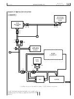
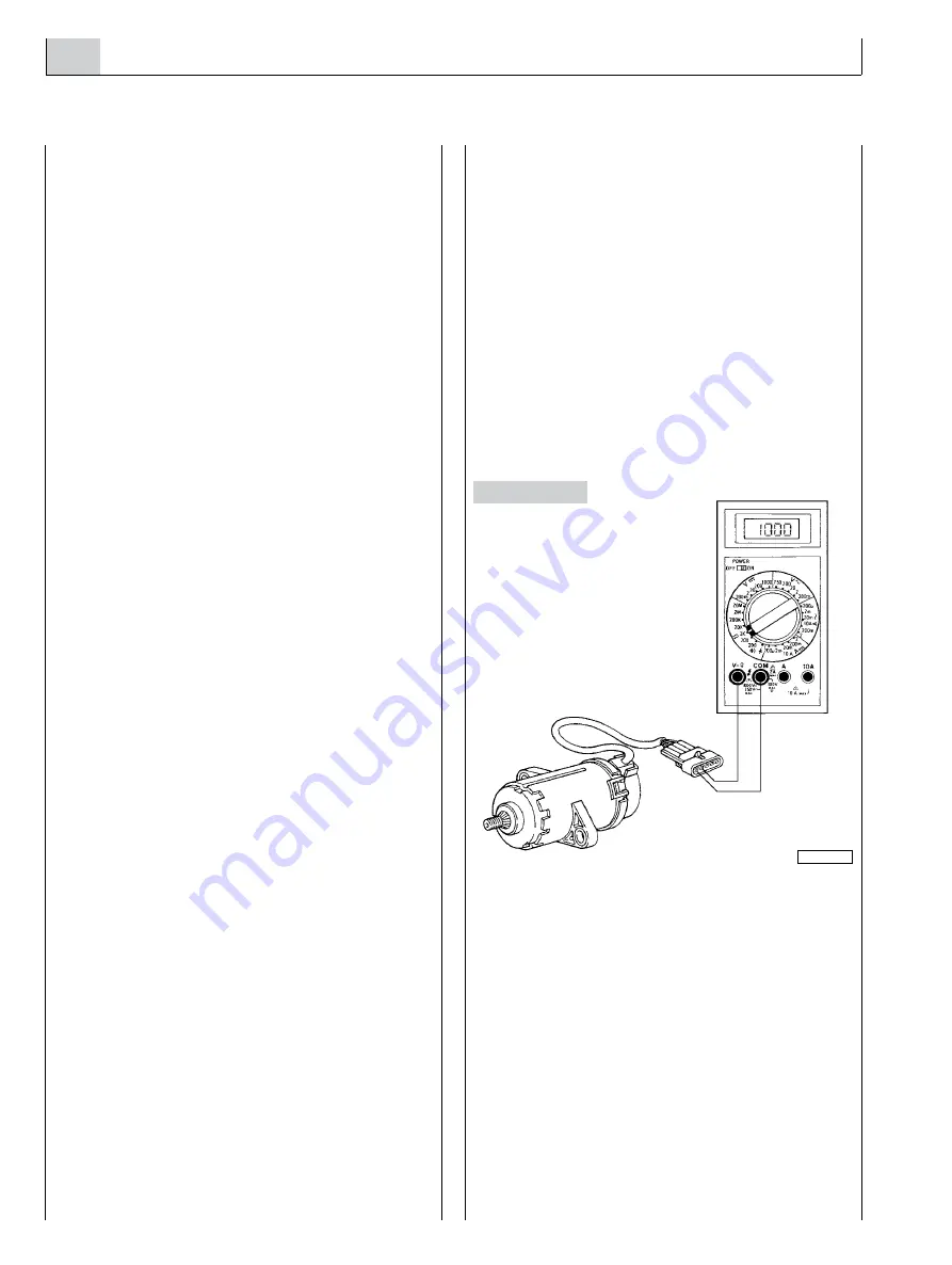
Throttle lever position sensor
In the positions of minimum and maximum travel, verify the
correlation between the position of the throttle control valve
on the bridge and the position of the sensor rod, checking:
o
That in the resting position the safety switch inside it is
electrically open. Carry out the test with an ohmmeter
between the points D and E of the potentiometer
connector.
- Value read
∞
Ω
= optimal adjustment;
- Value read 1 k
Ω
= a better mechanical adjustment of
the resting position is required, to bring the value back
to
∞
Ω
.
o
In the position of maximum acceleration, the rod of the
sensor has reached the mechanical end stop.
Instrument panel
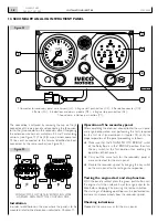
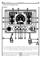
Verify the efficiency of all light indicators, as described in the
related Chapters.
04_080_N
Figure 42
18. TESTS BEFORE
THE FIRST START-UP
Содержание NEF N40-ENT-M25
Страница 64: ...INSTALLATIONDIRECTIVE 64 N40 ENT M25 N60 ENT M37 M40 MAY 2006 ...
Страница 69: ......

