installation directiVe
66
N40 ENT M25
N60 ENT M37-M40
MAY 2006
JB
JA
JF
B
EDC
JF1
A
JH
JH
JE
JE
JC
JC
JB1
JO
JD
JB
JB
JB
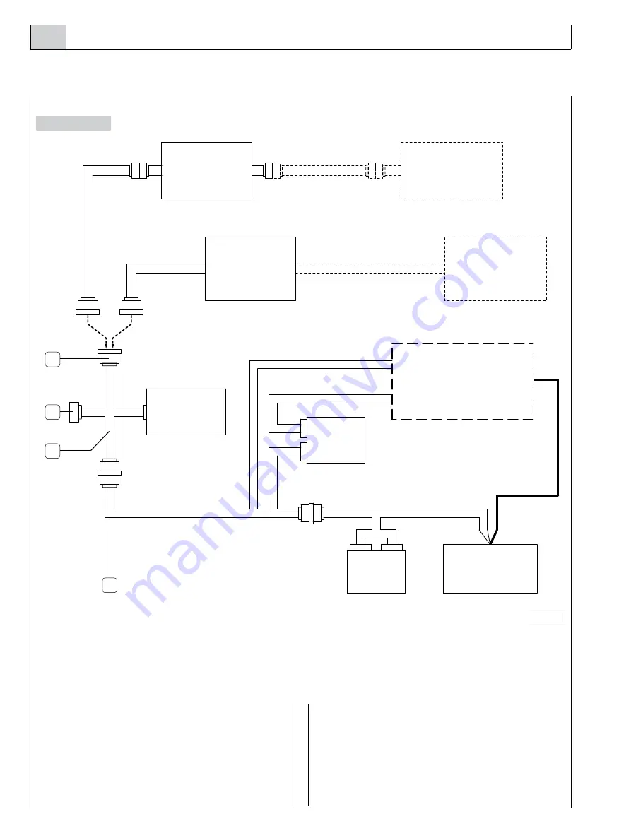
This option offers the chance, in alternative to that prepared
for the engine, electronic management of the engine rev.
speed.
Installation must take place inserting the interface wiring (2)
between the engine and the wiring of the control panels
to which the exterior governor will be connected and the
electronic module for converting the electric signals from the
lever into electronic information recognisable by the EDC
central unit.
If this solution is used the accelerator position sensor
installed on the engine will remain electrically connected but
unused and the EDC central unit will manage the engine
speed according to the power signal applied to the JD con-
nector terminals (3).
If the electronic acceleration system fails, it will be possible
to manage the engine rev speed in an emergency, by discon-
necting the JD connector and mechanically activating the
lever of the sensor installed on the engine.
05_041_C
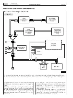
Figure 1
ELECTRONIC CONTROL GOVERNING LEVERS
1. Engine wiring connector for connection of the control panels - 2. Interface wiring for the installation of electronic control levers -
3. Connector for the connection of the exterior governor - 4. Conversion module for codifying the signals of the exterior governor.
4
3
2
1
For version with analogue instruments
enGine
eqipment
main
instrument
panel
secondary
instrument
panel
relay
box
battery
conVerter
module
main
customiZed
instrument
panel
secondary
customiZed
instrument
panel
Содержание NEF N40-ENT-M25
Страница 64: ...INSTALLATIONDIRECTIVE 64 N40 ENT M25 N60 ENT M37 M40 MAY 2006 ...
Страница 69: ......


