installation directiVe
25
N40 ENT M25
N60 ENT M37-M40
MAY 2006
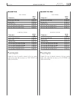
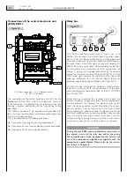
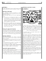
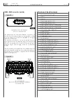
CONNECTORS OF THE JB - JC EXTENSION WIRE HARNESS, SEEN FROM THE COUPLING SIDE
To identify the functions served by the individual lines, refer to the electrical diagrams in Chapter 24.
1. JB-JC extension wire harness - 2. JE-JH extension wire harness.
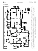
Figure 20
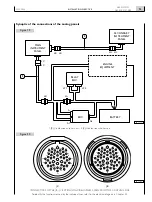
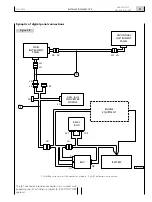
Figure 1
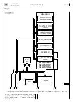
Synoptic of the connections of the analog panels
JB
JA
JF1
JF2
A2
A1
A
JH
JH
JE JE
JC
JC
04_254_N
1
2
main
instrument
panel
relay
box
edc
secondary
instrument
panel
battery
enGine
equipment
JC
JB
32
47
18
28
45
17
29
44
16
42
43
31
46
30
7
11
12
24
38
1
5
6
13
14
15
4
40
26
27
41
25
39
21
22
36
34
8
9
19
20
33
35
23
37
2
3
10
24
12
40
39
22
38
37
23
36
44
16
13
14
41
26
25
27
15
28
42
43
1
11 4
10
2
3
7
5
17
6
18
35
21
9
20
19
33
8
32
34
47
29
45
30
31
46
04_250_N
Содержание NEF N40-ENT-M25
Страница 64: ...INSTALLATIONDIRECTIVE 64 N40 ENT M25 N60 ENT M37 M40 MAY 2006 ...
Страница 69: ......


