installation directiVe
N40 ENT M25
N60 ENT M37-M40
MAY 2006
Connector JD
The JD connector enables to use an electronic engine rpm
management instead of the system provided on the engine.
If this solution is used, the throttle position sensor, situated
on the engine, will remain electrically connected but not
used and the EDC Central Unit will manage engine rpm
according to the voltage signal applied to the terminals of
the JD connector.
In case of a fault in the electronic throttling system, the engine
rpm may be managed in emergency condition, mechanically
operating the sensor lever positioned on the engine.
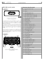
The connection requires a METRI PACK 150 four-way con-
nector with male terminals.
Figure 1
04_263_N
1
2
3
4
NOTE:
The voltage values for the rotation of the motor must be between 0.2 and 4.8 V. Values below 0.2 V or above 4.8 V
generate the recognition of a fault and consequent deactivation of the function.
pin
Wire code
(u) Voltage
interpreted function
i
max
1
7731
+B with key in ON position
Electronic throttle enabling
0,5 A
2
0000
0 V - (Ground)
Common reference terminal
-
3
5584
0 to 0,2 V
Poor value. EDC recognises a fault
-
0,2 to 0,5 V
Accelerator at minimum level
0,5 to 4,5 V
Accelerator min. to max., U function
-
4,5 to 4,8 V
Accelerator at maximum level
-
4,8 to 5 V
Excessive value. EDC recognises a fault
4
5551
Ground, with engine in overspeed Overspeed engine indication
0,1 A
Содержание NEF N40-ENT-M25
Страница 64: ...INSTALLATIONDIRECTIVE 64 N40 ENT M25 N60 ENT M37 M40 MAY 2006 ...
Страница 69: ......

