background image

Chapter 4

Getting Started 

 4-31

Type of Recorder

Hint

You can only set values in this submenu if you want to define a
new card format. See Appendix A "Define your own card format".

Two different types are available:

Standard recorder

Graphic recorder

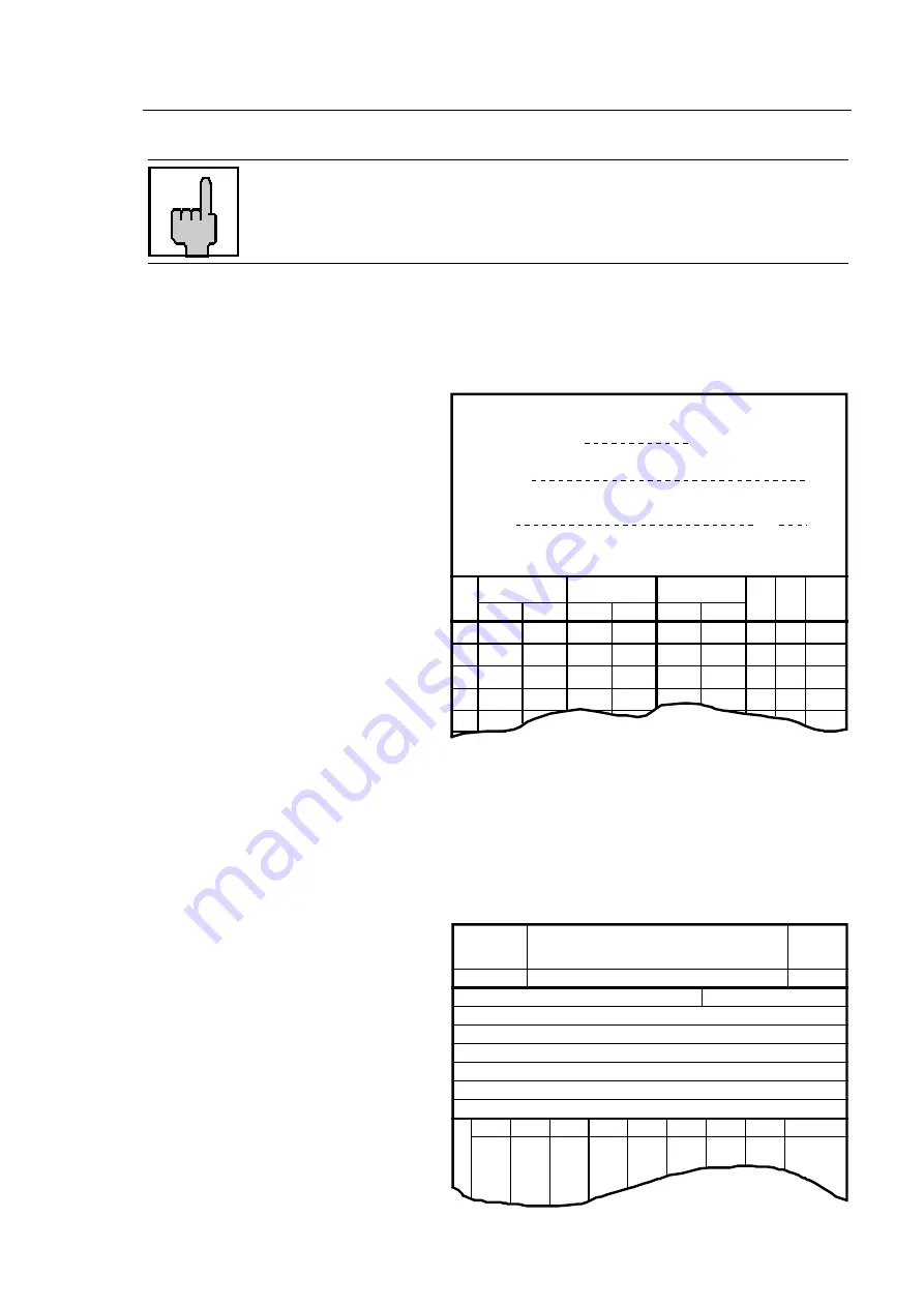
Standard recorder

The imprint on the time card will be
executed in lines according to the
day. The time card is separated in
an IN- and OUT-clocking columns.
The days are arranged vertically.

See separate card catalogue.

If you have defined a new card
format, you select whether one or
two card lifts per day shall be
executed.

Graphic recorder

The imprint on the time card is executed in columns according to the day. The card is
not separated in lines. Each column corresponds to one day of the current period.
Graphical cards may be folded, so that all days of one booking period, e.g. one
month, can be arranged on one card.
The recorder distinguishes in
graphic mode between a "leaping
imprint" and "creeping imprint".
With "leaping imprint" all IN- and
OUT-clockings are positioned in
defined distances.
With "creeping imprint" the
distances change according to the
time, the clocking is executed.
The advantage of a creeping
imprint: an "early IN-" or "early
OUT"-clocking can be seen on the
time card.

IN

OUT

OUT

IN

1

2

3

4

OUT

IN

Morning

Afternoon

Interruptions

and Overtime

Month

19

Name

No.

1

2

3

4

5

6

7

1

No.

Name

Page

Month:

Target Hours

Remarks:

Содержание Perfect 2020

Страница 1: ...PERFECT 2020 Product Manual ...

Страница 2: ...nterests without the prior written permission of ISGUS With the exception of component parts changes ISGUS has made every effort to keep the contents of this manual current and correct at the time of publication However we cannot guarantee the documentation to be 100 accurate Should you find any errors in this document please let us know We are always grateful for suggestions and comments from our...

Страница 3: ...d to comply with the Class B limits may be attached to this equipment However there is no guarantee that interference will not occur in a particular installation If this equipment does cause harmful interference to radio or television reception which can be determined by tuning the equipment off and on the user is encouraged to try to correct the interference by one or more of the following measur...

Страница 4: ...ty precautions All applicable local and national safety regulations must be observed in the installation use and maintenance of the time recorder Modifications to the time recorder made without the authorization of the manufacturer will negate the manufacturer s responsibility and liability Hints for the user Before installing and programming the time recorder the operator must read the operating ...

Страница 5: ...teed only when you use the manufacturer s original replacement parts Use of non conforming parts voids your warranty Unplug and switch the unit off immediately if a problem occurs in the electrical system Installation and mounting of the unit must be done by trained personnel Plug the time recorder power supply into a sufficiently grounded electrical outlet Ensure that all consumables and replaced...

Страница 6: ...1 Chapter 3 Installation 3 1 Chapter 4 Getting Started 4 1 Chapter 5 Operation 5 1 Chapter 6 Error Messages 6 1 Chapter 7 Maintenance 7 1 Appendix A Define Your Own Card Formats A 1 Appendix B Code Table B 1 Appendix C Summary Of Keyboard Commands C 1 Appendix D Technical Specifications D 1 ...

Страница 7: ...Chapter 1 Introduction 1 1 Chapter 1 Introduction Product Overview 1 2 How to Use This Manual 1 3 Symbols and Abbreviations 1 5 ...

Страница 8: ...ters and settings on a sheet of paper Before the recorder is programmed please note your time organization together with your individual time patterns and models This manual gives you step by step instructions on the operation of the PERFECT 2020 time recorder It documents all important functions which are available to users We recommend that you carefully read this manual before the commissioning...

Страница 9: ...ed teaches you how to prepare and program the time recorder for your application This chapter takes you through a step by step instruction guide on the programming panel setting of the date and time various menu items and options and how the programming routine works The programming via PC and other programming possibilities are described in a further paragraph Chapter 5 Operation explains how to ...

Страница 10: ...If you want a summary or to go in the programming and using of the recorder fast you can look in Appendix B Code table and Appendix C Keyboard commands Appendix D Technical specifications contains a summary of all technical data ...

Страница 11: ... instructions are not followed carefully Attention This symbol indicates that there may be danger to the time recorder if the text is not read or the procedure is not followed Data may be lost or the recorder may be damaged Hint This symbol indicates useful information and recommendations for the handling of the time recorder Digital display Mainly used in chapter 4 Getting Started The values prin...

Страница 12: ...Chapter 2 Features 2 1 Chapter 2 Features PERFECT 2020 2 2 Options 2 4 Accessories 2 4 Recorder Construction 2 5 Time Recorder Identification 2 6 ...

Страница 13: ...order can be used width 68 mm 106 mm 2 67 4 17 inch The print release on the time card is executed electro mechanical The current column is marked by a column pointer in the pointer field The pointer field shows the current illustration with the column separation of the card used This pointer field may be replaced by other funnel shields The printer head is positioned in the corresponding column e...

Страница 14: ...Select character order and print format out of default values Select character order and print format freely National identification for weekday Variable card lift Imprint with machine reference number Programming via PC Signal circuit Hint To program the recorder via PC you need program P2020 This program can be bought from your sales partner ...

Страница 15: ...lock function Hint A recorder can only be provided with one of the following functions Slave clock function or DCF connection The functions signal circuit and check of individuals exclude each other Only one of these two functions can be active Accessories Accessories Model 2020 Program P2020 with connection cable for programming via PC ...

Страница 16: ...8 Fig 1 Total view 1 Analogue clock 2 Digital display for date 3 Card funnel 4 Pointer field with funnel shield and column pointer 5 Programming Panel concealed by the front cover see chapter 4 Getting Started 6 Position key 7 Front case cover 8 Rear case cover ...

Страница 17: ...plate is fixed on the bottom side of the cover The serial number is attached to the inside bottom of the unit The label with the program data 1 can be found on the operating system PROM of the CPU Example P 2020 Type of recorder V 2 19 Program release Fig 2 PC board Type of recorder Electrical data ...

Страница 18: ...ral Conditions 3 3 Specific Conditions for the Time Recorder 3 3 Time Recorder Installation 3 4 Installation for Table Operation 3 4 Wall Mounting 3 5 Open the Recorder 3 6 Close the Recorder 3 7 Remove the Metal Back Plate 3 7 Wall Mounting 3 8 Connect the Power Supply 3 8 Connect Optional Features 3 10 ...

Страница 19: ...rating manual 3 Warranty Registration Card 4 2 keys 5 Power supply unit 6 Fixing elements for wall mounting 2 screws 2 plugs 7 Set of accessories for table operation 4 rubber feet 3 cover caps 8 Set of funnel shields Hint Time cards are not included with your time recorder and must be ordered separately Please contact your local dealer or e mail us at www sales isgustime com ...

Страница 20: ... being exposed to direct contact with any kind of liquid or steam there are no dirty manufacturing processes that could contaminate the location the location is isolated from electromagnetic noise sources such as motors electromagnets and series reactors Specific Conditions for the Time Recorder The time recorder is designed for continuous operation The time recorder is designed for indoor mountin...

Страница 21: ...additional options and the programming of the time recorder are carried out with the time recorder s case open Below the time display panel you will find a power switch and other electrical terminals and components Please refer to the section Programming panel Warning All work must only be carried out by qualified and authorized personal Installation for Table Operation When using the time recorde...

Страница 22: ...rds For the connection of additional functions such as slave clocks and or signal devices refer to section Wall mounting Wall Mounting The PERFECT time recorder is designed for table mounting However 120 VAC power connection and signal control terminals have been provided to meet the requirements of eventual wall mounting applications Installation steps 1 Open the time recorder 2 Remove the metal ...

Страница 23: ...ide of the time recorder Press the key into the slot until the locking latch releases the front case cover Fig 6 Unlock the recorder 2 Swing out the front case cover with the time recorder tilted away from you step 1 until it can be lifted up and off the time recorder step 2 1 2 Fig 7 Open the recorder ...

Страница 24: ...e locking latch on the bottom of the rear case cover Hint Do not close the time recorder until you have made all electrical connections and completed all time recorder programming Remove the Metal Back Plate 1 To begin removing the metal back plate press the two locking tabs located on the top left and right hand sides of the rear case cover step 1 2 Keep the locking tabs pressed in and push the m...

Страница 25: ...ll corresponding holes with a 5 16 drillbit Insert the wall plugs 3 Mount the metal back plate starting first with the lower screw and then the top screw Make sure you do not fully tighten 4 Using a carpenters level align the time recorder once more and then tighten both screws 5 Hang the time recorder mechanism on the wall mounted metal back plate The four metal tabs one on each corner of the met...

Страница 26: ...t the power cord is plugged into Incorrect connections can cause the destruction of the time recorder 3 Connect the power cable of the power supply unit to the bottom side of your PERFECT Fig 10 Bottom side of the recorder with power cable socket 4 Insert the plug in power supply unit into the provided socket Warning The power outlet must be close to the recorder and easily accessible Make sure th...

Страница 27: ...sed for both types of installation i e table or wall mounted version When used as a table unit the knockouts at the bottom of the metal rear back plate have to be used for cable entry For wall mounted units the plastic knockouts on the bottom of the rear cover have to be detached Fig 11 PC board with connection options 1 Power connection terminals 4 Battery standby connector 2 Signal circuit conne...

Страница 28: ...This connection is not polarity sensitive Connect an optional battery pack for printer operation during a power failure Attention This connection is polarity sensitive Connect impulse lines for slave clocks connection only if recorder is equipped with option module slave clock function unipolar and bipolar impulses 12 V 60 V 2 10 mA This connection is not polarity sensitive The Installation is now...

Страница 29: ... and Date 4 16 Setting the Time of the Internal Quartz 4 19 Synchronizing the Analogue clock 4 19 Setting the Date only 4 19 Programming Customer Requirements 4 20 Calling up the Programming Routine 4 22 Print out all Parameters Programmed 4 24 Language Identification 4 25 Daylight Saving Time Change over 4 25 Time Card Parameters 4 29 Select Card Format 4 29 Type of Recorder 4 31 Period Duration ...

Страница 30: ...t 4 49 Graphic Recorder with Creeping Imprint 4 50 Ribbon Colour Change 4 51 Change Erase Values for Ribbon Colour Ch 4 52 Signal Operation 4 53 Signal Times 4 54 Signal Out Programming 4 55 Quit Programming Mode 4 56 Set Options 4 60 Check of Individuals 4 61 DCF connection 4 62 Slave clock function 4 63 Standby Operation 4 63 Master Clock 4 63 Card Face Control 4 65 Commissioning after power fai...

Страница 31: ...internal reset is executed This reset has been executed in the factory A pre programmed card organisation was loaded into the recorder The time of the analogue clock is synchronised automatically with the time of the internal quartz clock Now the columns can be selected manually by the position key After the first switch on of the recorder it is now fitted with all parameters required for test ope...

Страница 32: ...tched on or if your time zone is not Eastern Standard Time you have to re set the time and date displayed D1 D2 D3 D2 Hours D3 Minutes Enter current hour with R Confirm with E Repeat steps 1 and 2 for minutes Set hands of analogue clock After time has been entered the current date is displayed For more details on setting date and time see section Setting the Time and Date 3 Close the unit and lock...

Страница 33: ... are available in the unit If you take a standard card format you can select the corresponding funnel shield out of the two plastic templates Separate the corresponding shield with a cutting knife For a clean cutting edge we recommend to use a guide strip The cutting lines are marked on the plastic bows In the upper left edge of the funnel shield language and field separation number of columns x c...

Страница 34: ...an adhesive point 1 Remove front cover 2 Insert funnel shield into pointer field Fig 13 Insert funnel shield 3 Check that the column pointer marks the right clocking column Execute a sample clocking and adjust the funnel shield centred to the clocking printed on the time card and the column pointer The big right angled opening left of the pointer field must not be covered Fix the funnel shield e g...

Страница 35: ...mum width of card funnel 68 mm Maximum width of card funnel 106 mm If the minimum card width of 68 mm is not reached a correct card guide cannot be guaranteed Proceeding 1 Open recorder Remove front cover 2 Connect power supply via separate mains cable Recorder is switched off Power switch in position 0 3 Remove rear panel of recorder See chapter 3 Installation fig 4 4 Switch recorder on Power swi...

Страница 36: ... adjustment 8 Adjust card guide See fig on the next page Open left guide rail with the two screws Insert card completely into card funnel If necessary move controller for card lift adjustment downwards by turning the transport spindle until the card can be inserted far enough into the card funnel Adjust guide rail to the card so that a safe card guide is possible The left guide rail have to be adj...

Страница 37: ...nd R again Keep both keys pressed until column pointer switches back to the first menu symbol time 11 Switch the recorder off and on Card lift adjustment is carried out and the controller for the card contact is set to the initial position 12 Set again metal rear panel of recorder Make a sample clocking before rear panel is set 13 Close recorder Put and engage front cover Adjustment is finished ...

Страница 38: ...t on the time card is irregular or too weak Hint If the recorder is adjusted to another card thickness the eccentric screws must be positioned exactly parallel to achieve a regular print upon the whole card width 1 1 Fig 16 Adjust card thickness 1 Left and right eccentric screw red The eccentric can be adjusted in steps by 5 100 mm Proceeding 1 Switch off recorder 2 Insert time card 3 Turn both ec...

Страница 39: ...e of subsequent changes have to be executed with the recorder opened The programming panel contains function elements which are only necessary to set the parameters and for service purposes Fig 17 Programming panel 1 Column pointer 2 Symbols for programming 3 Programming keys R E and S 4 Programming LEDs 1 7 5 6 digits display 9 3 6 12 D1 D2 D3 1 2 3 4 5 6 7 R E S 1 2 3 4 5 ...

Страница 40: ...E See section Set date and time Language identification Controls specific language of weekday See section Programming Language identification Daylight saying time change Several models are available See section Programming Daylight saving time change Time card parameters Selection of a certain card organisation type of recorder period duration current week and number of lines and columns In this m...

Страница 41: ...y entered Card lift timing for graphical cards See section Programming Card lift line change timing Ribbon color change The print color can be red or black The times for the ribbon color change can be defined for each weekday See section Programming Ribbon color change Signal circuit Check of individuals For the control of signal circuit or check of individuals external signal devices for example ...

Страница 42: ...item the S key will not move you to the next In normal operation column selection by position key Programming LED s 1 2 3 4 5 6 7 The seven LEDs are for weekday programming Each flashing LED represents the day for which the necessary change timing needs to be programmed LED 1 Monday to LED 7 Sunday Digital display D1 D2 D3 Separation into the fields D1 D2 and D3 When recorder is closed only field ...

Страница 43: ...artz clock In case of power failure the analogue clock will be synchronised with the internal quartz clock as soon as power returns power reserve The correct display of the current date is guaranteed by an eternal calendar If the recorder is used as master or slave clock or provided with DCF connection see in this chapter Set Options In this menu the following functions are available Setting the T...

Страница 44: ... marks the symbol for time Time is displayed 2 Example D1 D2 D3 Enter current hour using R D2 hour Value range 00 23 If you do not want to change the value displayed continue with step 3 3 Confirm the value using E Recorder switches to minutes 4 Example D1 D2 D3 Enter minutes using R D3 minutes Value range 00 59 The value entered should be set one minute before the desired reference time 5 Press E...

Страница 45: ... full hour entered and displayed In our example 10 h D1 D2 D3 9 3 6 12 Set minute hand first and then hour hand Both hands can be moved forwards and backwards If the minute hand is moved after the hour hand has been set the hour hand will be moved as well 7 Confirm each setting with E The synchronisation of the analogue clock will not start immediately Only when the date has been set the automatic...

Страница 46: ...ths with 31 days are available January March May 11 Confirm selection using E The recorder switches to input of year 12 D1 D2 D3 D3 year Value range 00 99 Proceed as described in the previous steps 13 Confirm selection using E After the last date input has been confirmed with E the analogue clock is synchronised If the synchronisation is finished the analogue clock works with the current time Reco...

Страница 47: ... 2 Proceed as described under the topic Set date and time A change of the internal quartz clock is always followed by a manual hand setting of the analogue clock and a synchronisation between quartz and analogue clock Synchronizing the Analogue clock If the time printed on a time card differs from the time of the analogue clock the analogue clock has to be synchronised with the internal quartz clo...

Страница 48: ...programming panel When the programming routine is started the column pointer switches to the second symbol Each menu items has to be selected and programmed or confirmed in chronological order The column pointer indicates the currently active menu item Different parameters are entered with special code numbers that are selected using R It is possible to switch to the next menu item or parameter by...

Страница 49: ...mming via PC Programming the recorder via PC is the easiest and most time saving way to adjust the recorder to your individual time organisation If you own a connection cable and the program P2020 we recommend to program the recorder via PC The program P2020 contains all parameters and programming functions like for the programming via the programming panel Additionally a help text is available fo...

Страница 50: ...am all parameters Language identification to Signal circuit Check of individuals Option Code numbers 4 7 1 1 Allows the user to program time specific values of the unit 1 8 8 8 Complete programming of the recorder If a wrong code number was entered the programming mode is left automatically Additionally to the entry of a wrong code number the programming mode can be left by pressing S To call up t...

Страница 51: ...anges to next digit 4 Enter second digit using R and confirm settings using E Repeat steps 2 and 3 for the other 2 digits 5 After the last digit has been confirmed using E the column pointer changes to the first menu symbol With code no 1888 Language identification With code no 4711 Daylight saving time Now the first value in the menu can be programmed With code number 4711 the column pointer chan...

Страница 52: ...his could damage the printer head The minimum card length has to be 210 mm Don t fall below the indicated dimensions The parameter values will be printed out when a menu item is left If you insert an empty card and press S all values programmed in the last menu will be printed out The print out begins with the menu item Card specific parameters The menu items National identification and Summer nor...

Страница 53: ...h 11 Norwegian 04 French 12 Finnish 05 Spanish 13 Polish 06 Italian 14 Russian 07 Portuguese 15 Turkish 08 Dutch 16 Greek Units destined for North America are pre programmed with language identification 02 If you do not want to change the value displayed continue as described in step 2 2 Press S for next menu item Daylight saving time Daylight Saving Time Change over The symbol is indicated by the...

Страница 54: ...nition 00 no change over 01 change over according to CET last Sunday in March 02 00 03 00 last Sunday in October 03 00 02 00 02 change over according to CET last Sunday in March 02 00 03 00 4th Sunday in October 03 00 02 00 03 change over according to GMT last Sunday in March 01 00 02 00 last Sunday in October 02 00 01 00 04 change over according to GMT last Sunday in March 01 00 02 00 4th Sunday ...

Страница 55: ... for freely programmed change over D1 01 Change over from normal to daylight saving time Date D2 day Select desired date using R Value range 01 31 Confirm selection using E D1 D2 D3 D3 month Select desired month with R Value range 01 12 Confirm selection with E D1 D2 D3 D1 02 Change over from normal to daylight saving time Time D2 hour Select desired hour with R Value range 00 23 If is displayed t...

Страница 56: ...ay hour D3 month minute Confirm each value with E In order to check all the introduced values with key E the whole menu item could be displayed step by step 4 Confirm menu with S to continue with next menu item Time card parameters After having confirmed the menu with key S the recorder makes a card lift adjustment This procedure lasts some seconds It is indicated by the noise of the transport spi...

Страница 57: ...ble and only these values are displayed If you want to define your own card format you will find all details concerning the proceeding in Appendix A Define your own card format Select Card Format A high number of time card formats have already been programmed and stored in the recorder If you use such a standard card format you have to indicate which card No and by this which card format should be...

Страница 58: ... Appendix A 01 xx Standard card formats card no see sep card catalogue Co Copy standard card formats Erase values for card format Copy function see Appendix A Units destined for North America are pre programmed with card format 29 2 Confirm selection with E If you have already been using a standard format and you want to alter only some values of this format we recommend to copy this standard form...

Страница 59: ... The imprint on the time card is executed in columns according to the day The card is not separated in lines Each column corresponds to one day of the current period Graphical cards may be folded so that all days of one booking period e g one month can be arranged on one card The recorder distinguishes in graphic mode between a leaping imprint and creeping imprint With leaping imprint all IN and O...

Страница 60: ...aphic recorder with creeping imprint ascending 05 Graphic recorder with creeping imprint descending Units destined for North America are pre programmed with type of recorder 05 consequence of setting card format no 29 Continue with E Next submenu Period duration Period Duration Hint You can only change any values setting if you have selected the value 00 or Co in the submenu Card format See Append...

Страница 61: ...tting card format no 29 Continue with E Next submenu Current week Current week The recorder must know the current week of the period Hint The current week can only be selected if the values 2 3 or 4 weeks have been entered in the submenu period duration Otherwise the submenu current week will be skipped and the recorder switches automatically to the next submenu Number of columns Proceeding 1 D1 D...

Страница 62: ...ns D1 D2 D3 D1 04 indicates the 4th submenu Number of columns D3 XX number of columns Units destined for North America are pre programmed with number of columns 07 consequence of setting card format no 29 Continue with E Next submenu Number of lines Number of Lines Hint If a standard card format has been selected the values shown in this submenu are pre set and cannot be altered The number of line...

Страница 63: ...ore can be set to any day of the month Hint With cards of a 5 week pay period capacity and automatic month end correction an eventual shifting of the start of the pay period is not feasible Proceeding 1 D1 D2 D3 Select start of pay period with R Value range 01 31 D1 06 indicates the 6th submenu start of pay period D3 xx day from 01 Monday to 07 Sunday Units destined for North America are pre progr...

Страница 64: ...tain number and the print format must be selected via this number Print example Field 4 Mark AM PM Field 3 example minutes Field 2 example hours Field 1 example date Available print formats of the unit not in full scale Format No Field1 Field2 Field3 Field4 Example 01 Weekday Hours Minutes 02 Date Hours Minutes 03 Hours Minutes 04 Weekday Hours 12 Minutes AM PM 05 Date Hours 12 Minutes AM PM 06 Ho...

Страница 65: ... printed in condensed letters Theses print formats should be used for time cards with very narrow columns graphical cards Examples not in full scale Format No Field1 Field2 Field3 Field4 Example 19 Weekday Hours Minutes 20 Date Hours Minutes 21 Hours Minutes 22 Weekday Hours 12 Minutes AM PM 23 Date Hours 12 Minutes AM PM 24 Hours 12 Minutes AM PM 25 Weekday Hours 1 100 hrs 26 Date Hours 1 100 hrs...

Страница 66: ...ours Minutes 39 Hours Minutes 40 Hours 12 Minutes AM PM 41 Weekday Hours 1 100 hrs 42 Date Hours 1 100 hrs 43 Hours 1 100 hrs 44 Hours 12 1 100 hrs AM PM 45 Weekday Hours 5 100 hrs 46 Date Hours 5 100 hrs 47 Hours 5 100 hrs 48 Hours 12 5 100 hrs AM PM If the print formats stored in the recorder are not enough you can create your own imprint The character order as well as the characters according t...

Страница 67: ...ed continue with step 4 If you have selected code 00 continue with step 3 3 D1 D2 D3 Define a print format For the print 5 fields are available see print example Not all fields have to be defined Definition is executed from left to right D1 01 first field D2 Type of field Value range 00 13 Possibilities 00 Blank space 01 Minutes 02 Decimal hours 5 100 03 3 minute leap 04 Decimal hours 1 10 05 Deci...

Страница 68: ...selection with E D1 D2 D3 Select desired imprint width with R Value range 1 4 Possibilities 1 narrow 2 cycles Dot e g 2 normal 3 cycles Dot e g 3 double 4 cycles Dot e g 4 bold 6 cycles Dot e g Confirm selection with E D1 D2 D3 to D1 D2 D3 Repeat the entry for the fields 02 03 04 and 05 as described for field 01 If you have not selected a freely defined character for the fields D2 09 or D2 11 cont...

Страница 69: ...ace will be set and printed automatically D1 D2 D3 to D1 D2 D3 Weekday freely defined D1 07 for Monday 08 for Tuesday 09 for Wednesday 10 for Thursday 11 for Friday 12 for Saturday 13 for Sunday In the fields D2 and D3 you have to enter a hexadecimal value which is printed in the code table on the next page This code table is based on the ASCII code Example Sunday 7Z D2 37 D3 5A Enter character wi...

Страница 70: ...is based on the ASCII Code In the table you can find the hexadecimal value for a character Any other characters are printed as blank spaces 0x 1x 2x 3x 4x 5x 6x 7x x0 Space 0 P x1 1 A Q x2 2 B R x3 3 C S x4 4 D T x5 5 E U x6 6 F V x7 7 G W x8 8 H X x9 9 I Y xA J Z xB K xC L xD M xE N xF O ...

Страница 71: ...ine your own card format If you have selected a standard card format these values cannot be changed Definitions D1 D2 D3 D1 00 to XX indicates the current column starting with D1 00 and the column width of the first column D2 and D3 D1 00 left card edge D2 D3 XX Current column width in mm value is pre set by the card format selected Accuracy 1 10 mm Example D1 01 D2 01 D3 0 5 D1 1 column D2 and D3...

Страница 72: ... D3 D1 00 to XX indicates the current line starting with D1 00 and the corresponding line value D2 and D3 D1 00 indicates the bottom line of the card D1 01 indicates the clocking field at a graphic recorder and the lowest clocking line at a standard recorder D2 D3 XX Line height in mm value given by the card format selected Accuracy 1 10 mm Example D1 01 D2 11 D3 0 0 D1 1 line clocking field D2 an...

Страница 73: ... Standard recorder with two card lifts day Graphic recorder Standard Recorder with One Card Lift per Day With a standard recorder each weekday is printed into a separate line The time values when to print in which column can differ from weekday to weekday Due to this all column change timings have to be programmed for each weekday Proceeding 1 1 2 3 4 5 6 7 D1 D2 D3 Select weekday with R The weekd...

Страница 74: ...3 minutes Value range 00 59 Confirm minutes with E 4 D1 D2 D3 Repeat step 3 for the remaining clocking columns and their timing 5 After the last column value has been entered press S 6 1 2 3 4 5 6 7 Select next weekday with R 7 1 2 3 4 5 6 7 Confirm weekday with E The LED lights permanently 8 D1 D2 D3 Repeat steps 3 to 7 for the remaining weekdays and their timing If the time values for the column...

Страница 75: ...he morning are printed in the first line and all clockings in the afternoon are printed in the second line See separate card catalogue card format no 06 The timing for the first line has to be programmed first then the timing for the second line The distinction between first and second line is displayed in field D1 D1 Line Column 11 first line of weekday left digit and 11 first clocking column rig...

Страница 76: ...weekday Card Lift Line Change Timing The symbol is indicated by the column pointer After the column change timing has been programmed in the last menu item the card lift timing has to be programmed in this menu You have to distinguish between Standard recorder Graphic recorder with leaping imprint See menu item Card specific parameters Type of recorder Graphic recorder Graphic recorder with creepi...

Страница 77: ...print The timing for the first upper line must be entered first The number of this line is the total number of lines If not all lines possible have an individual timing instead of the time value you can enter There will be no clocking in a line defined with Conditions 1 Menu Card specific parameters Type of recorder 03 2 Menu Imprint Print format selected or freely defined Line height is always 3 ...

Страница 78: ...09 01 09 21 09 41 10 01 10 21 10 41 11 01 11 30 11 45 12 00 12 15 12 30 12 45 13 00 13 15 13 30 14 00 14 20 14 40 15 00 18 01 16 30 16 00 15 40 15 20 Punching IN early Flexible time IN Coretime Lunch break Coretime Flexible time OUT Punching OUT late Graphic Recorder with Creeping Imprint Only two time values per day must be programmed if a graphic recorder with creeping imprint has been selected ...

Страница 79: ... values are valid for all weekdays Entries for each weekday via the LED panel are not required with graphic recorders Units destined for North America are pre programmed with upper imprint field 01 00 h lower imprint field 23 00 h Ribbon Colour Change The symbol is indicated by the column pointer The recorder offers the possibility to change between black and red imprint In this menu the point of ...

Страница 80: ...lues programmed can be changed at any time Proceed as described on this page Proceeding 1 Call up programming routine key R 2 Select menu Ribbon colour change key S 3 Select weekday with time value s to be Changed key R 4 Select time value to be Changed advance with key E 5 Change time value key R To Change further values on this weekday repeat steps 4 and 5 6 Quit time entry for this weekday key ...

Страница 81: ... low power signal output for the controlling of an external relay To this external relay it is possible to connect an external signal device If the unit is provided with the function check of individuals the function signal circuit is no longer available See section check of individuals Each function of menu Signal operation is divided into 2 parts and each part has its own menu symbol signal time...

Страница 82: ...timing standard recorder with one card lift per day D1 signal duration in seconds the belonging time value will be erased D2 Hours D3 Minutes Change or Erase Signal Times All time values programmed can be changed or erased at any time Details to the following proceeding can be find in the previous proceeding Proceeding 1 Call up programming routine key R 2 Select menu Signal times key S 3 Select w...

Страница 83: ...e the signal is switched off If no date to switch on the signal is programmed the signal will be switched on the following day Up to 16 dates can be programmed A programmed date can be changed or erased at any time The dates can be entered in any order it is not necessary to order the dates chronologically But the date to switch off the signal must be followed by the date to switch on All dates wi...

Страница 84: ...ith E The next value if programmed is displayed Example 00 01 01 01 06 01 00 24 12 01 31 12 and so on If the value 01 06 01 is erased the next 00 24 12 is displayed Now the menu can be left as described above or new values can be entered See proceeding on the previous pages Quit Programming Mode The programming mode is left automatically when the last menu item Signal out programming has been quit...

Страница 85: ...rd differs from the time of the analogue clock the synchronisation must be repeated See in section Set date and time Synchronise analogue clock at the beginning of this chapter If you wan to print out all parameter values you can start now Insert a protocol card and proceed as if you would program your recorder by calling up the programming routine Proceed further as described under the topic Prin...

Страница 86: ...olumns number of lines Menu Imprint Print format Menu Column change Clocking column width in mm Menu Card lift Line height in mm of clocking lines 1 value bottom line 1 value card edge Menu Column change timing Time values per weekday from 1 Monday to 7 Sunday Menu Card lift timing Time values per weekday Machine number Weekdays freely defined Example from left to right Number freely defined f e ...

Страница 87: ...ange Menu Signal out programming Menu Ribbon colour change Timing per weekday 01 black 02 red Menu Signal times Signal times per weekday with signal duration in seconds Menu Signal out programming Signal out periods during the year 01 Signal on 00 Signal off ...

Страница 88: ...ion Check of individuals cannot be released via this routine See paragraph Check of individuals on the following pages Proceeding 1 Switch recorder off 2 Keep R pressed and switch recorder on Keep R pressed until synchronisation of the analogue clock has finished 3 D1 D2 D3 Select status with R field D3 Definition D1 01 slave clock function 02 DCF connection 03 Standby operation 04 Master clock fu...

Страница 89: ...pre set ex factory This option can only be installed later if the complete CPU board is changed Hint The functions signal times and check of individuals exclude each other Both functions use the same circuit on the recorder CPU External signal devices e g horn lamp are switched on to defined times These signal devices are controlled by a random number generator The percentage programmed is basis f...

Страница 90: ...lled How this option can be released in the recorder please read section Set options on the previous pages Hint The functions DCF connection and Slave clock exclude each other as both functions use the same circuit on the option module and on the PC board When the option DCF connection is released the connection input will be scanned permanently on the option module If a signal is received the dec...

Страница 91: ... This option can be released if the battery pack has been installed How this option can be released in the recorder please read in this chapter on the previous pages Set options With this option the time recorder will print up to 300 registrations over a power outage period of 24 hours If the recorder is provided with the option DCF connection as well the recorder changes from DCF connection to th...

Страница 92: ...slave clocks need not to be set back 11 hours The slave clocks will not receive any pulses until the master clock has the same time as the slave clocks A built in current limit ensures that there will be no damage to the recorder in case of short circuit or overload at the slave clock output Proceeding 1 Call up Set date time with E see at the beginning of this chapter Set date and time 2 Set date...

Страница 93: ...lied Card Face Control If the card face control device is installed also the function has to be enabled in the unit See section Set Options The card face control prevents from punching on the wrong card side Commissioning after power failure The recorder need not be programmed after a power failure Normal operation is possible when power returns All parameter values and settings are stored in the ...

Страница 94: ...can be inquired Different ways of programming are possible Connect recorder with the PC execute programming at the PC and transfer values to the recorder Program all values on the PC without the recorder being connected save values in the PC and transfer the values to the recorder later General Conditions for the Program P2020 IBM compatible PC XT AT and higher with a pulse rate of not more than 1...

Страница 95: ...erface e g COM 1 or COM 2 The cable can also be plugged into COM 3 or COM 4 Open the recorder and switch it off Connect the cable with the rack and panel plug X4 of the recorder CPU The plug is coded and cannot be connected wrong Switch recorder on Start the program out of the subdirectory with the command C P2020 and press enter The info window appears on the screen The info window contains furth...

Страница 96: ...ettings and values on harddisk or diskette A file name has to be entered and if necessary the corresponding directory The file name must have to extension PAR This extension is added automatically by the recorder if you have not entered it Load Loading a file from harddisk or diskette which contains certain parameter values and settings programmed New Standardises the loaded programming file and s...

Страница 97: ...ion Punching at the Recorder 5 2 Standard Recorder 5 3 Clocking with Manual Column Selection 5 3 Clocking with Automatic Column Selection 5 4 Clocking with Mixed Column Selection 5 5 Graphic Recorder 5 6 Standby Operation 5 7 Save Values 5 8 ...

Страница 98: ...inting on the time card to be unreadable Requirements for Trouble Free Time Recording Always store time cards in a dry place Humidity can cause the time cards to expand so that they will not fit into the time recorder Keep the time cards in good condition and avoid mishandling damage such as corner bending folding and tearing Protect time cards against contamination from such as dirt dust and oil ...

Страница 99: ...nter field The printer head advances to the next clocking column with each pressing of the position key The column pointer advances from left to right Hint The position key is only for column selection and not for print release If the right clocking column is already marked you need not press the position key Proceeding 1 Current date is displayed The current date must correspond to the clocking l...

Страница 100: ...er this column can be selected with the position key When the clocking has been printed the column pointer switches back to the automatic column If the clocking column is selected manually and no clocking is executed the column pointer switches back to the automatic column after about 3 seconds Proceeding 1 Current date is displayed The date displayed must correspond with the clocking line on the ...

Страница 101: ...ng has been printed If no clocking is executed the column pointer switches back to the automatic column after about 3 seconds Proceeding 1 Current date is displayed The current date must correspond with the clocking line on the time card e g here line 21 Do you want to book an extra time Manual selection continue with step 2 Do you want to execute an IN or OUT clocking Automatic selection continue...

Страница 102: ...orrespond with the date on the funnel shield marked by the column pointer Possible imprints with graphical cards creeping imprint with start position at the bottom creeping imprint with start position at the top leaping imprint with start position at the bottom leaping imprint with start position at the top The start position always refers to the first clocking of a day More details and informatio...

Страница 103: ...d off and the time of the analogue clock is set according to the internal quartz clock If the unit is used as master clock all slave clocks will be provided with impulses In case of power failure the time recorder switches automatically to standby operation Standby operation is indicated by a flashing line in the right segment of the digital display To save battery capacity all sub functions e g a...

Страница 104: ...l values programmed in the recorder can be saved on harddisk diskette with the function Upload in the Main Menu of the program P2020 To save the parameter values of the recorder the connection cable between unit and PC has to be installed The PC device has to be plugged into terminal X4 on the recorder CPU Fig 18 Recorder CPU with terminal X4 ...

Страница 105: ...rouble Shooting 6 1 Chapter 6 Trouble Shooting Error Messages 6 2 Reset 6 4 Partial reset 6 5 Hardware test 6 6 Display printer and memory test 6 6 Test mode 6 7 PC board 6 8 Change of Fuse for Signal Output 6 10 ...

Страница 106: ...r Error not corrected change PC board RTC module error in real time clock component Punching at the recorder is no longer possible Switch recorder off and on If the error message is still displayed first carry out a complete reset Error not corrected change PC board Do not change only the RTC module as it is a SMD component Error in synchronization of the card lift mechanical error Punching at the...

Страница 107: ...ry Check ribbon and ribbon transport Ribbon may be twisted or pinched Program error can only happen when the recorder is switched on Switch recorder off and on If the error messages is still displayed the EPROM has to be changed Error not corrected change the complete PC board Reprogram the recorder after change of the PC board Wrong program An attempt was made to use an operating system PROM of a...

Страница 108: ...time values will be erased Now all columns can be selected manually the line change is executed daily at 00 00 h Thus a test operation is possible Additional to the partial reset the variable values of the real time clock component are set as follows Card lift line change adjustment 50 for no change Column change adjustment 50 for no change Analogue clock 00 00 After the reset the synchronisation ...

Страница 109: ...nto the recorder If necessary readjust the imprint of the recorder Partial reset A partial reset can be executed during normal operation Date card lift adjustment column change adjustment and analogue clock will not be altered The following parameters will be erased or set to default value Language identification 01 Daylight saving time change over 01 Time card parameter 01 Type of recorder Period...

Страница 110: ...y E is pressed simultaneously until the adjustment routine has finished In this test mode the display the printer and all the memories are checked When the test routine is started all the display elements are flashing The card lift is set automatically for the print out of the test report The test routine can be interrupted by pressing any key and is started as soon as a time card is inserted into...

Страница 111: ...itched off and a month with 31 days can be advanced manually by a key To start the test mode please press R and then S Please keep both keys pressed for about 1 second The time 00 00 and the current date 01 is displayed The simulated month starts with a Monday The current weekday is indicated by the LED s With the key R the minutes and with E the weekday can be altered If the key R is pressed for ...

Страница 112: ...erminal for signal operation floating contact Contact max 250 V 5 A 3 X3 Terminal step motor for card lift adjustment 1 yellow 2 red 3 orange 4 brown 4 X3 Terminal step motor for printer spindle 5 blue 6 red 5 X3 Terminal slide contact 7 green 8 green 6 X3 Terminal card contact for print release 9 black 10 black 7 X7 Interface operator board Display LED s keys 8 Terminal for option module MASTER C...

Страница 113: ...cessary for a qualified test The test runs must be performed under dynamical conditions and therefore they cannot be performed locally Attention Pay attention when using testing spikes for a manual test The plug contacts of the IC socket must not be damaged Always test at test point 11 against ground A measurement between the wrong test points will lead to a damage of the PC board TP Designation M...

Страница 114: ... The fuse in the external power supply is meant for the unit itself Use only fuses with the same technical data See appendix A Technical Specifications Attention Before changing the fuse switch off the unit and disconnect the power supply 1 Open the unit with the key and remove the front cover 2 Disconnect the power supply see illustr 3 Switch off the unit 4 Slightly pull out the fuse from the fus...

Страница 115: ...Chapter 7 Maintenance 7 1 Chapter 7 Maintenance Adjustment Routine 7 2 Changing the Ribbon 7 3 Cleaning the Time Recorder 7 4 ...

Страница 116: ...hanges are in steps of 0 1 mm Minimum dimensions of the card left card edge 3 5 mm bottom line 16 5 mm Card lift line change To check the position the imprint programmed is printed in the first column valid on 01 01 00 at 01 23 which usually is the first line After each clocking a column change is executed If a graphic unit is used the clocking is orientated on the upper line of the imprint field ...

Страница 117: ...distance between left card edge and clocking is increased Shift clocking to the left with E The distance between left card edge and clocking is decreased Step width 0 1 mm Example Adjustment value 41 clocking is shifted 0 9 mm to the left 7 Repeat adjustment and sample clocking until the horizontal position of the clocking is correct Press S to quit adjustment routine Changing the Ribbon To change...

Страница 118: ...is inserted in front of the printer head and that the ribbon is not twisted or creased The ribbon cassette must engage into the left and right locking straps 6 Check that the ribbon fits between the printer head and the ribbon guide Tighten the ribbon again 7 Swing in the programming panel Press R and E once again see step 2 The column pointer moves back to initial position 8 Close the time record...

Страница 119: ...A Define Your Own Card Format Create a New Card Format A 2 Time Card Parameters A 2 Type of recorder A 2 Period duration A 4 Number of columns A 5 Number of lines A 6 Column change A 7 Card lift line change A 8 Adjust a Pre programmed Standard Format A 9 ...

Страница 120: ...ers If the value 00 has been programmed in the menu Time card parameters the following parameters have to be programmed Type of recorder Period duration Current week Number of columns Number of lines Attention If the card format is altered the following values will be erased Dimensions for column change and card lift Times for column change and card lift Times for ribbon colour change Type of reco...

Страница 121: ...ith creeping imprint has been selected you can choose between ascending and descending imprint Ascending imprint First clocking of the day will be printed on the bottom of the card Descending imprint First clocking of the day will be printed on the top of the card Attention If the card format is altered the following values will be erased Dimensions for column change and card lift Times for column...

Страница 122: ...standard and graphic recorders Monthly start position 1 column or 1 line continuous imprint The recorder starts with the imprint in the 1 line 1 column Space lines space column will not be noticed Monthly 1 line free continuous imprint The recorder starts with the imprint in the 2 line 2 column 1 line 1 column of each page will be left free Monthly last line or last column of the first page free T...

Страница 123: ...r of columns In this submenu the number of columns on the time card used which has to be programmed The number of clocking columns can differ from time card to time card The number is either pre set or can be selected within a certain range depending on the type of recorder selected If a standard recorder is used the number of columns can differ between 1 and 8 If a graphic recorder is used the nu...

Страница 124: ...e made as graphical cards have only one line the imprint field If a standard recorder is used the number of lines is pre set by the period duration selected Period duration 01 1 week Number of lines 7 Number of lines 14 if 2 lines day 02 2 weeks Number of lines 14 03 3 weeks Number of lines 21 04 4 weeks Number of lines 28 05 5 wk with correct Number of lines 21 06 09 monthly Number of lines 16 21...

Страница 125: ...een programmed as number of columns the column width for each column is displayed in this menu For a card format freely defined the values displayed can be altered according to the card format If the column widths for the next columns have been erased the value of the previous column is displayed as default value If the column width remains the same confirm the column width displayed with E The ac...

Страница 126: ...ed imprint field The value 01 in the field D1 indicates the height of the imprint field D1 line 00 bottom line 01 xx clocking line at the standard recorder The line No will be increased automatically 01 Imprint field for graphic recorder D2 D3 line height in full mm D3 right digit line height in 1 10 mm If the recorder will be programmed new the first entered value will be displayed again for the ...

Страница 127: ... standard format does no more correspond to your requirements you can alter the format All time values e g for card lift will remain The number of the format copied must be the same as the standard card format used before Erase values of a card format With Copy you can erase all card specific values if the command is entered into field D2 instead of the card number to be copied Exception All value...

Страница 128: ... a standard card format will be changed into a card format to be freely defined The value erases all card specific parameters of standard card format resp a card format freely defined 4 Confirm with E 5 D1 D2 D3 During the card format is copied resp erased the display shows Recorder switches to the next menu Imprint Proceed as described in this chapter under the topic Create a new card format Any ...

Страница 129: ...Appendix B Code Table B 1 Appendix B Code Table ...

Страница 130: ...in March last Sunday in October change over acc to CET last Sunday in March 4th Sunday in October change over to GMT last Sunday in March last Sunday in October change over to GMT last Sunday in March 4th Sunday in October 00 01 02 03 04 change over to EEZ last Sunday in March last Sunday in October change over to EEZ last Sunday in March 4th Sunday in October change over to USA 1st Sunday in Apri...

Страница 131: ...09 04 Number of columns Code Standard recorder 1 to 8 columns Graphic recorder 7 columns 1 week or monthly Graphic recorder 14 columns 2 weeks Graphic recorder 8 columns monthly with start pos 1 or 2 Graphic recorder 16 columns monthly with start pos 1 or 2 xx 07 14 08 16 05 Number of lines Code Standard recorder 7 lines 1 week only if period duration 01 Standard recorder 14 lines 2 weeks only if ...

Страница 132: ... 9 dots Small 5 x 7 dots raised Small 5 x 7 dots centred 1x 2x 3x Small 5 x 7 dots hanging Cross 7 x 5 dots read from right Cross 7 x 5 dots read from left 4x 5x 6x Character width Code y left display digit Character width Code y left display digit Small 2 Cycles Dot Normal 3 Cycles Dot y1 y2 Double 4 Cycles Dot Bold 6 Cycles Dot y3 y4 Column change Setting Code 01 xx Clocking column Code Entry xx...

Страница 133: ...lour change Setting Code Ribbon colour black Ribbon colour red code entry xxxx Timing in HH MM 01 02 xxxx Signal Setting Code Code Entry xxxxxx Signal duration in seconds 2 digits Time to switch on in HH MM 4 digits xxxxxx x Check of individuals Setting Code Code Entry xx Percentage xx Signal out programming Setting Code 00 Signal off 01 Signal on code entry xxxxxx on off 2 digits Date in DD MM 4 ...

Страница 134: ... Option enabled 00 01 Slave clock function DCF function Standby operation Master clock function Card face control 01 02 03 04 05 Protection with Code Numbers Setting Code Setting Code Programming of all time values in the recorder 4711 Complete programming of the recorder 1888 ...

Страница 135: ...ard commands C 1 Appendix C Keyboard Commands Keyboard commands C2 Keyboard Commands for Programming C 2 Keyboard Commands for Punching C 2 Keyboard Commands on Error Messages C 3 Keyboard commands for maintenance C 4 ...

Страница 136: ... How to control the programming routine R Changing the values displayed selection of parameter values and settings E Entry confirmation of selection S Column switch to next menu item Print out the values programmed S push an empty card 210 long slightly down R H approx 2 sec Set options Controlling the option routine R Set status define type of impulse for slave clocks E Confirmation and advancing...

Страница 137: ...Commands on Error Messages Key Function E Er 10 Error on data transfer Confirm with E partial reset R E S H approx 2 sec Complete reset recorder is switched off All values in the recorder will be erased including date time Controlling E Confirmation and advancing at time and date R Selection of date and time R E S approx 2 sec Partial reset recorder is switched on Parameter values are set to defau...

Страница 138: ...order is used R S End of test mode Keyboard commands for maintenance Key Function E S approx 2 sec Calls up adjustment routine recorder is switched on Controlling the card lift adjustment R moves imprint upwards E moves imprint downwards S Switches to column adjustment Controlling the column adjustment R moves imprint to the right E moves imprint to the left S quits the adjustment routine R E appr...

Страница 139: ...Appendix D Technical Specifications D 1 Appendix D Technical Specifications ...

Страница 140: ... 80 non condensing Connection Standby operation Option Slave clock function Option 12 60V 2 10mA unipolar bipolar impulses Master clock Option Output 12V 50mA max Signal circuit see item Signal operation Determination of time Quartz Pola Signal circuit Low power signal output 15 V DC 50 mA Fuse 50 mA T Printer 9 dot matrix printer Battery pack Nominal voltage 12 V Nominal capacity 600 mAh Discharg...

Отзывы: