


iES26GF
User’s
Manual
UM-iES26GF-1.2.3-EN.docx
Pages 14 of 169
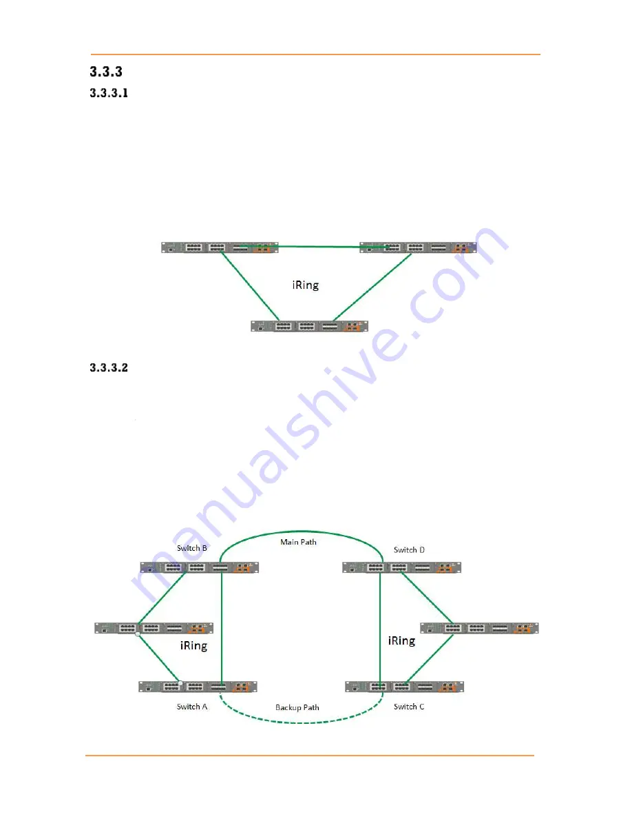
iRing/iChain
iRing
Three or more switches can be connected to form a ring topology with network redundancy
capabilities by following the steps below.
1.
Connect each switch to form a daisy chain using an Ethernet or fiber optic cable.
2.
Set one of the connected switches to be the master and make sure the port setting of each
connected switch on the management page corresponds to the physical ports connected. For
information about the port setting, refer to Section 5.4.1 iRing Configuration.
3.
Connect the last switch to the first switch to form a ring topology.
Figure 10 - Ring Topology
Coupling Ring
If two iRing topologies exist and you would like to connect the rings, a coupling ring can be
formed. Select two switches from each ring to be connected, for example, switch A and B from Ring
1 and switch C and D from Ring 2, then decide which port on each switch will be used as the coupling
ports and then link them together. For example, port 1 of switch A to port 2 of switch C and port 1 of
switch B to port 2 of switch D. Then, enable Coupling Ring on the management page and select the
coupling ring in correspondence to the connected port. For more information on port setting, please
refer to Section 5.4.1 iRing Configuration. Once the setting is completed, one of the connections
will act as the main path, while the other will act as the backup path.
Figure 11 - Coupling Ring
Содержание iES26GF
Страница 74: ...iES26GF User s Manual UM iES26GF 1 2 3 EN docx Pages 69 of 169 Figure 74 Unaware and C port Port Types...
Страница 75: ...iES26GF User s Manual UM iES26GF 1 2 3 EN docx Pages 70 of 169 Figure 75 S port and S custom Port Types...
Страница 101: ...iES26GF User s Manual UM iES26GF 1 2 3 EN docx Pages 96 of 169 Figure 102 QCE Configuration interface...


