


Optidrive P2 Elevator User Guide V2.30
43
Comfort Optimisation
www.InvertekDrives.com
13.
Comfort Optimisation
Note : It is recommended to initially perform the below tests with a lower speed/Maintenance/Inspection speed and load (in balanced
condition) and then gradually build up to the required operating speeds and load, Use P1-01 (Max speed limit) to limit the motor speed and
return back to normal value afterwards.
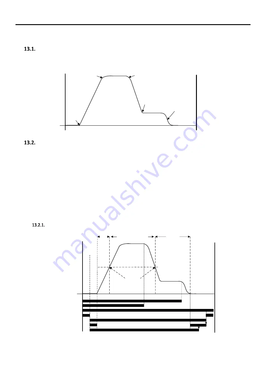
Ramp and travel Jerk Adjustment diagram.
The setting of the speed ramps and travel jerks are detailed in the diagram below and should be adjusted according to the application and
prior to setting the speed Loop Gains.
Accel
start Jerk
(P3-01)
Start
End
Accel
end Jerk
(P3-02)
A
cc
el
t
im
e
(P
1-
03
)
Decel
start Jerk
(P3-03)
Decel
end Jerk
(P3-04)
Run Speed (P2-02)
Levelling Speed (P2-02)
Stopping
Jerk
(P3-05)
D
ec
el
tim
e (
P1
-0
4)
Speed Loop Gains
The setting of the speed loop gains defines how closely the actual motor speed follows the given speed reference, in the case of an Elevator
the correct setting of the speed loop gains is critical in order to provide optimum comfort levels.
The speed loop gains are available in all motor operating modes except “Enhanced V/F IM Speed Control mode” (P4-01=2).
From default the drive has 1 set of speed loop gains enabled, Proportional Gain (P4-03) and Integral Gain (P4-04), these 2 gains are active
throughout the whole of the travel curve (Start, Travel and Stop).
A further set of speed loop gains, Low Speed Proportional Gain (P4-15) and Low Speed Integral Gain (P4-16) are also available for situations
where a different set of values are required for low speed (Take-off and Levelling) compared to high speed travel, the transition point between
the Low speed gains and high speed gains is determined by the value set in parameter P4-17 (Low speed Gains Transition Point).
A rollback gain parameter (P7-13) is also available, the rollback gain is generally only required in Gearless applications however it can also be
used in Geared systems.
Speed Loop Gains diagram.
Direction Input
High Speed Input
Motor Contactor Close (Relay 1)
P3-06
Motor Contactor Close/Open delay time (P3-06)
Drive Output on
P3-07
Brake Released (Relay 2)
Rollback
Gain
(P7-13)
Run Speed Gains (P4-03/P4-04)
Low to Run
speed Gains
transition point
(P4-17 rpm)
P4-15/
P4-16)
(P4-15/P4-16)
Direction input
P3-08
P3-10 = Zero speed holding time.
P3-10
P3-06
P3-06 = Motor Contactor Open/Close time.
P3-07 = Brake Release time.
P4-15 = Low speed loop P-Gain.
P4-16 = Low speed loop I-Gain.
P3-08 = Brake Apply delay time.
High Speed Input
Motor Contactor Control (Relay 1)
Drive Output
Motor Brake Control (Relay 2)
Motor Contactor Open/close actuation delay allowance.
Motor Brake Apply/release actuation delay allowance.
Start
End
Note: If P4-17 is zero then P4-15 and P4-16 will have no effect.


