


Optidrive P2 Elevator User Guide V2.30
19
Electrical Installation
www.InvertekDrives.com
Control Terminal Configuration.
P1-13 defines the function of each of the control terminals and should be set to match the connected controller.
Digital Input Configuration Parameter (P1-13)
The below table assumes the drive already has a direction command given i.e. Terminal 2 or 3 input is high.
P1-13
Digital Input 3(T4)
Digital Input 4 (T6)
Digital Input 5 (T10)
Active Speed
1
(Option 1)
Default
1
0
0
P2-02 (High Speed)
0 or 1
0
1
P2-03 (Intermediate Speed)
0 or 1
1
0 or 1
P2-04 (Inspection Speed)
0
0
0
P2-01 (Levelling Speed)
2
(Option 2)
1
0
*1
P2-02 (High Speed)
0 or 1
1
*1
P2-04 (Inspection Speed)
0
0
*1
P2-01 (Levelling Speed)
3
(Option 3)
1
0
0
P2-02 (High Speed)
0 or 1
1
0
P2-04 (Inspection Speed)
0
0
0
P2-01 (Levelling Speed)
4
(Option 4)
1
0
**1
P2-02 (High Speed)
0 or 1
1
**1
P2-04 (Inspection Speed)
0
0
**1
P2-01 (Levelling Speed)
5 (Option 5)
Brake release monitoring function see section 14.4 for details
6
(Option 6)
(Multispeed
Selection)
0
0
0
P2-01
1
0
0
P2-02
0
1
0
P2-03
1
1
0
P2-04
0
0
1
P2-05 (For rescue mode only)
(Max 5.0Hz)
1
0
1
P2-06
0
1
1
P2-07
1
1
1
P1-01
7 (Option 7)
1
0
0/1 (1 = Rescue mode enable)
P2-02 (High Speed)/
P2-05 (rescue speed)
0 or 1
1
0/1 (1 = Rescue mode enable)
P2-04 (Inspection Speed)/
P2-05 (rescue speed)
0
0
0/1 (1 = Rescue mode enable)
P2-01 (Levelling Speed)/
P2-05 (rescue speed)
1= Input High
0 = Input Low
* If 0 the drive will trip on “
” or
if a motor thermistor fitted and Ptc-th has been selected in P2-33.
** If 0 drive will fast stop using deceleration ramp in time set in P2-25., if P2-25 is zero the drive will coast to stop.
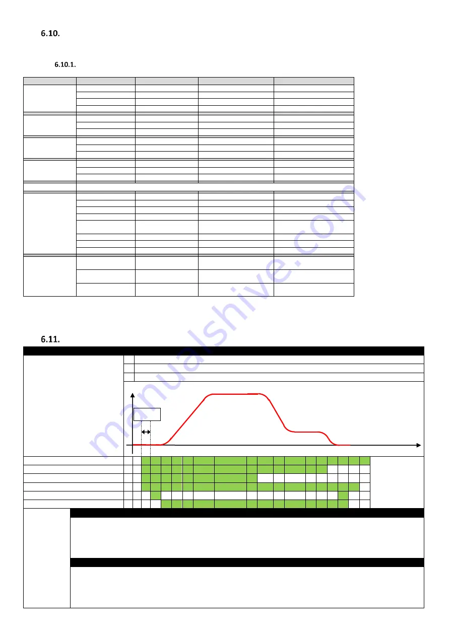
Motor Contactor Control
Related Parameters
Action
P3-06 (OUTPUT CONTACTOR
CLOSING TIME/RUN COMMAND
DELAY TIME)
1 Ensure advanced parameter access is enabled by setting P1-14 = 101
2 If Motor contactor activation is to come from the drive set P2-15 to 8.(Relay 1 output function select)
3 Program parameter
P3-06
as per the profile diagram below.
STO Input (T12+ T13)
Enable & Direction Input (T2 or T3)
Run Speed Input (T4)
Motor Contactor Close (Relay 1)
Zero speed Holding (IM motor only)
Drive Output Enabled
P3-06
(OUTPUT
CONTACTOR
CLOSING
TIME/RUN
COMMAND
DELAY TIME)
If Elevator controller is being used for motor contactor activation
Sets a delay time between the enable signal being applied to the drive and the drive energising the motor.
This ensures that an output contactor between the drive and motor has had enough time to close before the drive output comes on.
A value too low in this parameter may cause over current trips/Excess wear on the Contactor/Motor.
Note : When the drive is started it will remain in a “StoP” state until the value in P3-06 has elapsed, however if the start command signal is
toggled in the time less than P3-06 then the drive will not carry out the delay time and the drive output will come on immediately.
If drive is being used for motor contactor activation (P2-15=8) via Relay 1
Use P3-06 to set the delay time required for the relay contacts to close/open.
When the Enable (Run) signal is applied to the drive, the drive will signal the contactor to close, and then wait for the delay time set in P3-06
before applying torque to the motor.
When the Enable (Run) signal is removed from the drive, the drive will signal the contactor to open after the time set in
P3-06 has elapsed.
Run Speed
Speed
Time
P3-06
Levelling Speed


