


Optidrive P2 Elevator User Guide V2.30
21
Electrical Installation
www.InvertekDrives.com
Motor Holding Brake control-Option 2
If the brake Apply Speed (P3-09) parameter is set to zero (default setting), an additional parameter (P3-08) is used to define the time that the
drive should wait whilst holding the motor at zero speed prior to signalling the brake to close.
Related Parameters
Action
P3-07
(Brake Release Time)
P3-08
(Brake Apply Delay)
P3-10
(Zero Speed Holding
Time on disable)
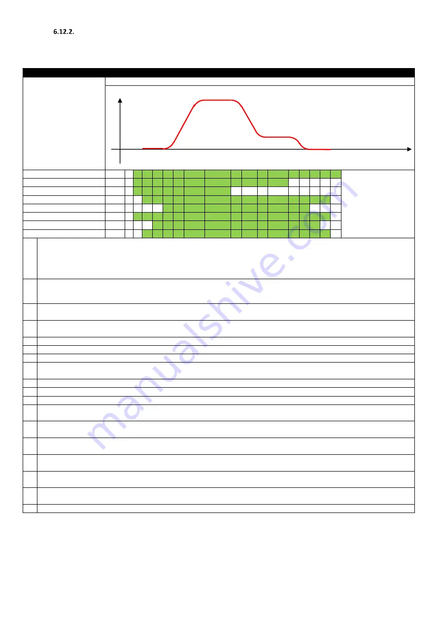
Program parameters as per the profile diagram below.
A B C D E F G H I J K L M N O P Q
STO Input
Enable & Direction Input
Run Speed Input
Drive Output Enabled
Output Frequency >0
Motor Contactor Output
Brake Control Output
Drive Enabled Output
A
STO Input Closed by external control system
Run Forward / Run Reverse input applied by External Control System
Run Speed (High Speed) Input Closed by External Control System
Motor Contactor Output (Relay 1) set by drive (to close motor contactor)
Drive waits for Output Contactor Closing Time (P3-06) before enabling the output stage to drive the motor
B
After the Motor Contactor Delay (P3-06) time has elapsed, the Drive Output to the motor is enabled at zero speed
Drive holds zero speed on the output, and magnetises the motor (IM Motor)
For PM Motor, the magnetizing time is zero
C
After the Motor Magnetizing Time has elapsed, the motor brake control output (Relay 2) is set to release the motor brake
The output Frequency remains at zero until the Motor Brake Release Time (P3-07) has elapsed
D
After the Motor Brake Release Time (P3-07) has elapsed, the drive output frequency is ramped up.
The Ramp Rate is controlled initially using Acceleration S-Ramp 1 (P3-01)
E
The Acceleration rate is now controlled linearly by the Acceleration Ramp Parameter (P1-03)
F
As the Run Speed is approached, the acceleration is now controlled by Acceleration S-Ramp 2 (P3-02)
G
Operation at Run Speed (P2-02)
H
When the Run Speed Input is removed, the drive output frequency is reduced to the Levelling Speed (P2-01).
Deceleration is initially controlled by Deceleration S-Ramp 1 (P3-03)
I
After Deceleration S-Ramp 1 (P3-03) has completed, deceleration is controlled linearly by the Deceleration Ramp Parameter (P1-04)
J
As the output frequency approaches the Levelling Speed (P2-01)., Deceleration S-Ramp 2 (P3-04) is applied
K
The drive operates at the Levelling Speed (P2-01) until the Direction Input is removed
L
On removal of the Direction input, the output frequency is reduced towards zero, with deceleration rate initially controlled by Levelling
S-Ramp (P3-05)
M
If the deceleration time is long enough to require linear deceleration , Deceleration Ramp Time (P1-04) is used
As the output frequency approaches zero, Levelling S-Ramp (P3-05) is again applied
N
The Output frequency reaches zero.
The drive holds at zero frequency and waits until the Motor Brake Apply Delay Time (P3-08) has elapsed
O
When the Motor Brake Apply Delay (P3-08) has elapsed, the Holding brake control relay opens (relay 2),so that the motor brake applies.
The drive output remains enabled at zero frequency for the Zero Speed Holding Time (P3-10)
P
When the Zero Speed Holding Time (P3-10) has elapsed, the drive output is disabled
The Motor Output Contactor signal remains on for the time period set in the Motor Contactor Delay Parameter (P3-06)
Q
After the Motor Contactor Delay Time (P3-06) has elapsed, the motor contactor output switches off allowing the motor contactor to
open
R
The STO Input to the drive can now be opened by the control system
Speed
Time


