


Optidrive P2 Elevator User Guide V2.30
41
Start-up of Gearless (Permanent Magnet) Motor-With Encoder Feedback.
www.InvertekDrives.com
Step 7a- Stationary Encoder offset measurement
(Alternative to rotating measurement).
An Encoder Offset measurement (Offset between motor poles and magnets) must be carried when operating a gearless motor.
This measurement should be used if the ropes cannot easily be removed from the motor, it should be noted that this measurement is not as
accurate as the Rotating Encoder Offset measurement (as per detailed in section 12.8), and may result in higher operating currents.
Action
Additional Information
Ensure elevator car is in a no-load balanced position within the shaft (i.e. with brakes off lift car should not naturally move). Failure to do
so will risk an incorrect encoder offset value.
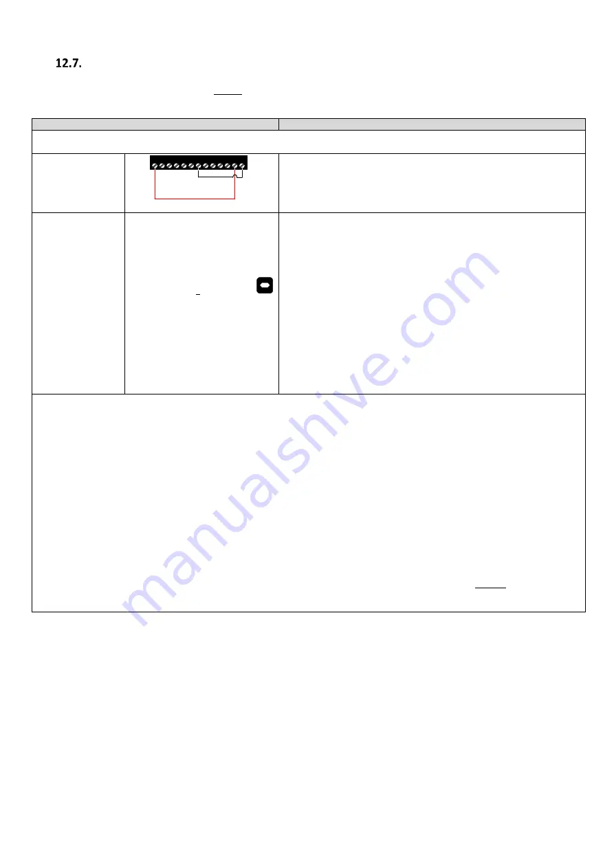
Check Safe Torque
off inputs have been
made.
1 2 3 4 5 6 7 8 9 10 11 12 13
Drive should now show
if not refer to the troubleshooting section at
the back of the user manual.
Stationary Encoder
offset measurement
Set P4-02 to a 2 and press the
button.
1.
The motor contactors will close (if controlled by the drive “Relay 1”,
and
providing the Safety chain is closed), if not controlled by the drive.
2.
The motor brakes will remain applied.
3.
The display will show
. (Test procedure may take several
minutes to complete).
4.
During the measurement the drive will inject a pulsating current into the
motor which will give a small sheave movement in order to measure the
offset value, therefore it is normal for a pulsing noise to be heard, if this
is not the case ensure that the motor contactors are closed and that the
encoder is enabled P6-05=1.
Note: The amount of movement can be observed in P0-78 (0-360°) and is governed by
the setting of P1-08, P4-07 and the strength of the motor brake.
5.
Once the Auto-tune is completed P4-02 will return to 0 and the display
will show
and P6-09 (Encoder offset value) will be populated.
Note on Stationary Encoder offset measurement:
1.
It is recommended that the stationary Encoder offset measurement test is repeated (with motor sheave in different positions) several
times to ensure that offset value is correct.
2.
The drive and motor current ratings must be correctly matched in order for the stationary encoder offset measurement to be accurate.
3.
Offset measurement will need to be repeated if the encoder is changed or mechanically moved.
If within repeated tests, the value shown in P6-09 is varying significantly (more than 50° ), or always a value of 0 then :
Increase P4-07, e.g 200 to 250 (increasing too high will result in overcurrent trips).
If Inconsistent values (with sheave in different positions) are still being measured or nuisance trips are occurring then
alternatively :
1.
Carry out the “Rotating Encoder offset measurement” (ropes-off) as per detailed in section 12.8.
or
2.
Run the drive in open loop as detailed in section 15 “Gearless (Permanent Magnet) Motors-Without Encoder (P4-
01=3). During steady state travel the encoder offset value will be displayed in parameter P0-78 index 2 (press up
arrow, value shown will be in the range 0-360).
Once steps 1 through to 7 above have been performed go to Section 13 Comfort Optimisation.


