Intermec EasyCoder 501 – Service Manual Ed. 7
204
Chapter 26 Troubleshooting
No memory backup storage
• If setup values, programs, layouts, date and time, or the like
which are saved in RAM, turn out to be lost, the trouble could
be a defi cient battery backup. In this case the message “Setup
lost” will appear on the display when the printer is switched
on.
• The minimum voltage of a suffi ciently charged battery after
power-off is 3.5V. The battery voltage must never drop below
3V during power-off at normal operating conditions.
Switch on the printer and check that the battery is being
charged. Voltage over R-324 should be 1–1.4V.
• If the battery is not properly charged, the reason is often that
the diode D-307 has been damaged, for example by RAM
packages having been fi tted upside down. The damage will not
reveal itself before the battery is empty and the memory is lost,
which may take weeks. If the diode is damaged, it must be
replaced
1
. Refer to Chapter 17.6:13 for circuits diagram.
• When installing a printer, always recharge the internal battery
by leaving the printer switched on for at least 24 hours.
No communication (general)
The following actions are valid for all communication interfaces
installed in the printer. Refer also to trouble shooting of the inter-
face in question.
• Check that the interface cable is correctly inserted and that it is
of correct type and confi guration.
• There are several ways to fi nd out what parameters a certain
printer interface is set up for:
- If the printer is fi tted with an Intermec Shell startup program,
there are various ways for printing or reading the setup, see
the Installation & Operation manual for the printer model in
question.
- You could also enter the Setup Mode. Most standard startup
programs and the immediate mode of Intermec Fingerprint
allow you to make use of the <Setup> key, provided the
printer has a keyboard.
- In case of EasyCoder 501 S printers without Intermec Shell
Standard, you may emulate an EasyCoder 501 E by fi tting a
Service GAL and a Service Keyboard, see Chapter 25.1.
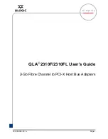
1
/. On CPU-board 1-040700-30 the
surface-mounted diode D-307 (BAR-
45C SMD) can be replaced by two
Schottky diodes 1N5818 soldered to
through-hole positions D-307A (imme-
diately above the battery B-300) and
D-307B (next to potentiometer WR-1),
see Chapter 17.5 and below.
B300
P201 C203
R324
D307A
D307B
D307
D200
WR1
DISP
Replacement
Diode 1N5818
Replacement
Diode 1N5818
Damaged
Diode D-307
26.2 Single Function
Failure, cont.