


SECTION 2
"
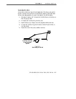
Installation Instructions
RT5900 SERIES Mobile Mount Radio Data Terminal
2-5
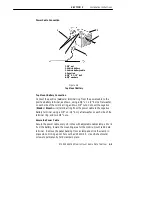
Power Cable Assembly
The power cable
must
have an in-line fuse installed
before
making final
connections to the vehicle battery. You must also crimp the 3/8 inch termi-
nal rings to the wire ends.
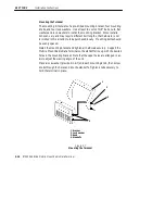
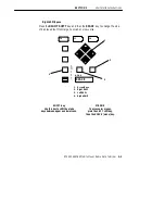
Assembling the In-line Fuse Holder
The in-line fuse holder consists of a rubber boot, two crimp-type fuse clips,
and a 15 amp fuse. Carefully follow these instructions to assemble the in-
line fuse holder.
1. Locate the in-line fuse holder components.
2. Cut the red wire in the gray power cable, midway between its end
and the gray cable jacket. Save the 6-7 inch length of red wire.
3. Strip approximately 1/4-inch of insulation from the red wire that ex-
tends from the power cable; also strip 1/4-inch of insulation from
both ends
of the 6 inch length of red wire saved in step #2.
4. Slide the longer portion of the in-line fuse holder boot (yellow rub-
ber) over the red wire that extends from the power cable.
5. Slip a fuse clip onto this wire and crimp the clip onto the wire.
6. Slip the remaining fuse clip onto one end of the 6 inch wire saved
from step #2 and crimp securely.
7. Slide this wire into the other half of the fuse holder boot. Insert the
fuse into the fuse clips and snap the halves of the fuse holder boot
together.


