background image

Intel® Server System M20NTP1UR - System Integration and Service Guide


76 


6.13


Processor Replacement 

Components Required: 


New matching 3

rd

 Gen Intel® Xeon® processor Scalable pro included shipping tray 


Existing processor carrier clip 


New processor heat sink or existing processor heat sink + new thermal interface material (TIM) 

Required Tools and Supplies 


Anti-static wrist strap, an ESD safe workbench, and other anti-ESD precautions (recommended) 


ESD Gloves (recommended) 


T-30 Torx* screwdriver 


1.


Power off the system and disconnect all cable from the back of the system. 

2.


Remove the system top cover (see 

Section 6.1.1

). 

3.


Remove the Air Duct (see 

Section 6.2.1

) 

4.


Remove riser card assembly (see 

Figure 76

). 

5.


Identify and locate the faulty processor. 

6.


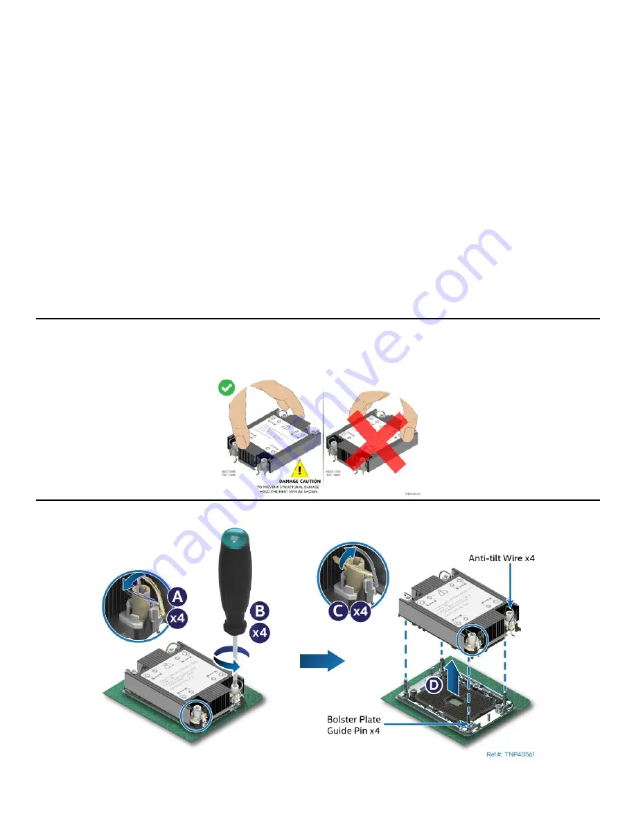
Remove the PHM from the server board (See 

Figure 96

) 

Caution:

 Fin edges of the processor heat sink are very sharp. Intel recommends wearing thin ESD protective 

gloves when handling the PHM during the following procedures. Processor heat sinks are easily damaged if 

handled improperly. See the following image for proper handling:  


Figure 96. PHM Assembly Removal from Processor Socket 

Содержание M20NTP1UR

Страница 1: ...and Service Guide A guide providing instructions for the insertion and extraction of system components and available Intel accessories and spares Rev 1 0 February 2022 Delivering Breakthrough Data Ce...

Страница 2: ...2 This page intentionally left blank...

Страница 3: ...Intel Server System M20NTP1UR System Integration and Service Guide 3 Document Revision History Date Revision Changes February 2022 1 0 First Public release...

Страница 4: ...oppel or otherwise to any intellectual property rights is granted by this document The products described may contain design defects or errors known as errata which may cause the product to deviate fr...

Страница 5: ...pening it Otherwise personal injury or equipment damage can result Electrostatic Discharge ESD Electrostatic discharge can damage the computer or the components within it ESD can occur without the use...

Страница 6: ...with a pair of fine needle nosed pliers If your jumpers do not have such a tab take care when using needle nosed pliers to remove or install a jumper grip the narrow sides of the jumper with the plier...

Страница 7: ...n 28 3 1 1 System Top Cover Removal 28 3 1 2 System Top Cover Installation 29 3 2 Air Duct Removal and Installation 30 3 2 1 Air Duct Removal 30 3 2 2 Air Duct Installation 30 3 3 Power Supply Module...

Страница 8: ...Drive Replacement 60 6 6 1 Drive Carrier Extraction 60 6 6 2 3 5 Drive Replacement 61 6 6 3 2 5 Drive Replacement 62 6 6 4 Front Drive Installation 64 6 7 Riser Card Replacement 65 6 8 OCP Module Repl...

Страница 9: ...onto Server Board 25 Figure 17 Tighten Heat Sink Fasteners 25 Figure 18 DIMM Blank Removal 26 Figure 19 Memory Module Installation 26 Figure 20 System Top Cover Screws 28 Figure 21 System Cover Remova...

Страница 10: ...60 Memory Module Removal 57 Figure 61 DIMM Installation 57 Figure 62 System fan assembly removal 58 Figure 63 System fan assembly installation 59 Figure 64 Power Supply Removal 59 Figure 65 Power Supp...

Страница 11: ...Processor Socket 76 Figure 97 Processor Socket Cover Installation 77 Figure 98 PHM Disassembly 78 Figure 99 Processor Carrier Clip Removal from PHM Assembly 78 Figure 100 Installing Processor Carrier...

Страница 12: ...1UR Reference Documents and Support Collaterals 15 Table 2 PCIe NVMe Cable Routing 38 Table 3 Intel Server System M20NTP1UR Features 46 Table 4 System Status LED State Definitions 50 Table 5 Recommend...

Страница 13: ...ed The Intel Server System M20NTP1UR supports up to 16 DDR4 DIMMs providing high memory bandwidth for memory intensive workloads For a complete overview of system features and functions refer to the f...

Страница 14: ...its used to enhance the base system feature set Chapter 4 System Software Update and Configuration A short overview describing the system software stack installed on new Intel servers and where to get...

Страница 15: ...e Intel Integrated Baseboard Management Controller Web Console Integrated BMC Web Console User Guide Public Base specifications for the IPMI architecture and interfaces Intelligent Platform Management...

Страница 16: ...onfigure save and restore various system options Intel Server Configuration Utility SYSCFG Various operating system support Public Intel Server Configuration Utility User Guide Product Warranty Inform...

Страница 17: ...hen skip this chapter and go to Chapter 3 for installation procedures associated with all other system options and accessories Figure 2 Intel Server System M20NTP1UR Features Before You Begin Before i...

Страница 18: ...top cover is necessary when installing or replacing any system component within the server chassis The system ships from the factory with the top cover secured to the chassis using three screws 1 Rem...

Страница 19: ...Top Cover Installation To maintain proper air flow within the system the top cover must be in place when the system is operating 1 Install the top cover See Figure 5 Figure 5 System Cover Installation...

Страница 20: ...ift the air duct straight up and away from the server system 2 2 2 Air Duct Installation To maintain proper air flow within the system the air duct must be in place when the system is operating 1 Ensu...

Страница 21: ...per processor Included with system 1U heat sink Included with system Required Tools and Supplies Anti static wrist strap an ESD safe workbench and other anti ESD precautions recommended ESD Gloves rec...

Страница 22: ...t within the PHM assembly includes a Pin 1 indicator Pin 1 indicator alignment between all components is required throughout the assembly process 1 Orient and align the processor carrier clip to the p...

Страница 23: ...tom side up onto a flat surface 3 Remove the plastic protective film if present from the Thermal Interface Material TIM 4 Place the heat sink Top side up onto a flat surface 5 Attach the heat sink to...

Страница 24: ...touch the socket pins The pins inside the processor socket are extremely sensitive A damaged processor socket may produce unpredictable system errors Figure 14 Processor Socket Cover Removal Remove t...

Страница 25: ...nto Server Board Set all four anti tilt wires on the heat sink to the inward position see Letter A Carefully lower the PHM over the four bolster plate alignment pins see Letter B Ensure the PHM is sit...

Страница 26: ...al Open the ejection tabs at both ends of the selected memory slot to lift the DIMM blank from the slot see Letter A Carefully remove the DIMM Blank from the system see Letter B Note DIMM Blanks shoul...

Страница 27: ...ory module with the key in the memory slot see Letter B Insert the memory module into the slot see Letter C Push down on the memory module until the ejection tabs snap into place see Letter D Ensure t...

Страница 28: ...an illustration first format This format gives the reader the option to follow a quicker path to component integration by first seeing an illustration of the intended procedure If necessary the reade...

Страница 29: ...slide the top cover 10mm towards the back of the chassis see Letter C Carefully lift the top cover up and away from the chassis 3 1 2 System Top Cover Installation 1 Place and secure the top cover to...

Страница 30: ...Air Duct Removal Lift the air duct straight up and away from the server system 3 2 2 Air Duct Installation To maintain proper air flow within the system the air duct must be in place when the system...

Страница 31: ...5 Power Supply Installation Slide the power supply into the power supply bay until it clicks and locks in place Note A single power supply configuration requires that the power supply bay insert be in...

Страница 32: ...move the screw securing the filler panel to the riser assembly see Letter A Remove the filler panel from the add in card slot see Letter B Insert the add in card until it is fully seated within the PC...

Страница 33: ...rmation 3 5 Front Drive Installation The Intel Server System M20NTP1UR has four front drive bays All drive bays require a drive carrier designed to support a supplied drive blank 3 5 HDD SSD or 2 5 SS...

Страница 34: ...drive carrier face plate to release the lever see Letter A Using the lever pull the drive carrier from the drive bay see Letter B 2 Remove the drive blank from the drive carrier See Figure 30 Figure...

Страница 35: ...until all mounting tabs lock in place 3 5 3 2 5 Drive Assembly Installing a 2 5 SSD into the 3 5 drive carrier requires that the supplied drive blank be used as a mounting bracket for the SSD Note In...

Страница 36: ...Install the SSD assembly into the drive carrier See Figure 34 Figure 34 3 5 Drive Carrier to 2 5 SSD Bracket Mount Bracket Assembly to Carrier Orient the SSD so that its interface connector is positio...

Страница 37: ...y to the carrier side rail See Letter G 3 5 4 Front Drive Installation 1 Install the drive carrier assembly into a front drive bay See Figure 36 Figure 36 Drive Carrier into Chassis Installation Align...

Страница 38: ...connector on the server board to a 3 pin cable header on the backplane See Figure 37 Figure 37 NVMe Support Cable Connectors The SlimSAS cables in the kit have specific lengths to support optimal rou...

Страница 39: ...uct see Section 3 2 1 4 Locate and unpack the cables from the cable kit 5 Select a cable and attach it to the identified connectors from Table 2 Repeat for each cable 6 Assemble and Install NVMe SSDs...

Страница 40: ...ly into one of the three mounting holes on the server board see Letter A Rotate the M 2 SSD latch assembly 90 degrees counter clockwise to secure it to the server board see Letter B 6 Install the M 2...

Страница 41: ...ver 1 Power off the system and disconnect the power cable s 2 Remove the system top cover see Section 3 1 1 3 Remove the Air Duct see Section 3 2 1 4 Remove the riser card assembly see Figure 26 5 Rem...

Страница 42: ...ur screws from the OCP stand offs on the server board See Figure 43 Figure 43 OCP Module Mounting Screws See Letter E 8 Mount the OCP module to the server board See Figure 44 Figure 44 OCP Module Inst...

Страница 43: ...ee Section 3 1 1 3 Remove the Air Duct see Section 3 2 1 4 Remove the riser card assembly see Figure 26 5 Locate and unpack the TPM accessory kit TPM module mounting hardware 6 Locate the 16 pin TPM c...

Страница 44: ...the Intel Server System M20NTP1UR Technical Product Specification 1 Power off the system and disconnect the power cable s 2 Remove the system top cover see Section 3 1 1 3 Remove the Air Duct see Sect...

Страница 45: ...tem A full software stack is installed during the system manufacturing process but may not be the latest available Intel highly recommends updating the full system software stack to the latest availab...

Страница 46: ...el Xeon processors are not supported Supported Processor Thermal Design Power TDP Maximum 185 W PCH Chipset Intel C621A Platform Controller Hub PCH chipset Embedded features supported on this server s...

Страница 47: ...2 external USB 3 0 connectors Back panel I O Two 2 external USB 3 0 connectors Front panel I O One 1 USB 3 0 internal onboard Type A connector Serial Ports One 1 DB 9 COM1 port cable connector Back pa...

Страница 48: ...option China compatible iPC JNPTPMCH Note Available TPM Accessory options are not supported by Microsoft Windows Server 2022 Onboard Jumper Blocks and Buttons System Buzzer Configuration Jumper Serial...

Страница 49: ...Intel Server System M20NTP1UR System Integration and Service Guide 49 Figure 48 Back Panel Features Figure 49 Front Panel Features Figure 50 Backplane Cable Connectors Figure 51 Control Panel Features...

Страница 50: ...any errors Source power is present BMC has booted and manageability functionality is up and running Blinking Green System is operating in a degraded state but still functional System is operating in a...

Страница 51: ...Reset the BIOS to its original default settings Reset the Real time clock Clear any BIOS security passwords The server board includes several 3 pin jumper blocks Most are used for factory support purp...

Страница 52: ...d in and directed to the high heat areas within the system the following requirements must be followed while the system is operational External ambient air in front of the system is between 10 C and 3...

Страница 53: ...has been powered off and AC power cord s and all other cables have been disconnected from the server system Before You Begin Before integration of any system components review all the safety and ESD p...

Страница 54: ...stem The top cover may be secured to the chassis using three screws one on each side and one on the top If present the screws must be removed before attempting to remove the top cover 1 Power off the...

Страница 55: ...o the chassis See Figure 57 Figure 57 System Cover Installation Align and place the top cover on the top edges of the chassis Slide it towards the front of the chassis until it locks into place see Le...

Страница 56: ...uct See Figure 58 Figure 58 Air Duct Removal Lift the air duct straight up and away from the server system 6 2 2 Air Duct Installation To maintain proper air flow within the system the air duct must b...

Страница 57: ...d Open the ejection tabs at both ends of the selected memory slot see Letter A The memory module will lift out from the memory slot Holding the memory module by its edges lift it away from the slot se...

Страница 58: ...mely high speeds Do not attempt to replace a system fan until it has stopped completely Attempting to remove a fan that is not completely stopped may result in injury 1 Power off the system and remove...

Страница 59: ...are trapped beneath the fan module see Letter B 6 5 Power Supply Replacement Required Tools and Supplies Intel spare power supply kit iPC AXXBFP750SLPS Anti static wrist strap and conductive workbench...

Страница 60: ...i static wrist strap and conductive workbench pad recommended Phillips head screwdriver for installing 2 5 SSDs Note To ensure proper system airflow requirements all drive bays must be populated and a...

Страница 61: ...carrier See Figure 68 Figure 68 3 5 Drive Installation to Drive Carrier Position the drive interface connector towards the back of the drive carrier Align and position the mounting holes on the left...

Страница 62: ...Figure 70 2 5 Drive Mounting Bracket Removal from Drive Carrier Step 2 Hold the carrier assembly top side down in your right hand Using your left hand gently rotate the bottom edge of the left rail up...

Страница 63: ...drive bracket using two screws See Letter E 7 Install the SSD assembly into the drive carrier See Figure 73 Figure 73 2 5 Drive Assembly Installation to Drive Carrier Step 7 Orient the SSD so that its...

Страница 64: ...sembly to the carrier side rail See letter G 6 6 4 Front Drive Installation 1 Install the drive carrier assembly into a front drive bay See Figure 75 Figure 75 Drive Carrier into Chassis Installation...

Страница 65: ...tic wrist strap and conductive workbench pad recommended Phillips head screwdriver 1 Power off the system and disconnect all cables from the back of the system 2 Remove the system top cover see Sectio...

Страница 66: ...card 8 Install the riser card to the riser card bracket See Figure 79 Note The riser cards are not interchangeable between the riser card slots on the server board Riser card slots on the server board...

Страница 67: ...10 Install the riser card assembly into the system See Figure 81 Figure 81 Riser Card Assembly Installation Position the two riser card edge connectors over the riser card slots on the server board A...

Страница 68: ...top cover see Section 6 1 1 3 Remove the Air Duct see Section 6 2 1 4 Remove the riser card assembly see Figure 76 5 Extract the OCP Module from the system See Figure 82 Figure 82 OCP Module Removal...

Страница 69: ...he server board See Figure 83 Figure 83 OCP Module Installation Carefully align and insert the cable connectors on the back edge of the OCP module through the opening s on the system back panel Gently...

Страница 70: ...the back of the system 2 Remove all drive carriers from the front drive bay 3 Remove the system top cover see Section 6 1 1 4 Remove all cables attached to the backplane 5 Carefully remove the backpl...

Страница 71: ...andle the card by its edges 7 Orient the backplane with all cable connectors facing the back of the chassis 8 Place and attach the backplane to the backside of the drive bay Figure 87 Backplane Instal...

Страница 72: ...Rotate the top edge of the backplane so the three mounting holes fit over the screw mounts on the drive bay See Letter E Figure 89 Backplane Installation Step 3 Using 3 screws secure the backplane to...

Страница 73: ...ide the blue latch away from the M 2 SSD see Letter A Carefully lift the free end of the M 2 SSD see Letter B and gently pull it out of the connector 6 Locate and carefully unpack the replacement M 2...

Страница 74: ...ee Section 6 1 1 3 Remove the system air duct see Section 6 2 1 4 Remove the riser card assembly see Figure 76 5 Carefully remove the Intel VROC Key from the server board See Figure 92 Figure 92 Intel...

Страница 75: ...ery Removal Gently press the metal latch to release the battery see Letter A Remove the battery from the socket see Letter B Dispose of the battery according to local laws 6 Locate and unpack the repl...

Страница 76: ...mended T 30 Torx screwdriver 1 Power off the system and disconnect all cable from the back of the system 2 Remove the system top cover see Section 6 1 1 3 Remove the Air Duct see Section 6 2 1 4 Remov...

Страница 77: ...ect that the processor socket is free of damage or contamination Note If debris is observed within the processor socket blow it away gently Do not use tweezers or any other hard tools to remove the de...

Страница 78: ...ink See Figure 99 Figure 99 Processor Carrier Clip Removal from PHM Assembly Unlatch the hook on each corner of the processor carrier clip and lift it from the heat sink see Letter D To properly reass...

Страница 79: ...re 100 Installing Processor Carrier Clip onto Processor Part 1 With the processor still in its tray place the processor carrier clip over the processor Ensure the Pin 1 indicator on the processor carr...

Страница 80: ...ting thermal interface material TIM from the bottom of the heat sink Apply new TIM DOWSIL TC 5888 If using a new heat sink Remove the plastic protective film if present from the Thermal Interface Mate...

Страница 81: ...s inside the processor socket are extremely sensitive A damaged processor socket may produce unpredictable system errors Figure 105 Processor Socket Cover Removal Remove the protective cover by squeez...

Страница 82: ...PHM Installation onto Server Board Set all four anti tilt wires on the heat sink to the inward position see Letter A Carefully lower the PHM over the four bolster plate alignment pins see Letter B Ens...

Страница 83: ...dule from the server board see Section 6 8 6 If Present Remove the Intel VROC Key from the server board see Section 6 11 7 If Present Remove the M 2 SSD from the server board See Section 6 10 8 Remove...

Страница 84: ...110 Figure 110 Server Board Installation 19 Re attach all cables previously removed from the server board 3 power cables 1 Main Power 2 CPU Power 6 fan cables 1 SATA MiniSAS HD cable If configured 4 N...

Страница 85: ...using one of the support phone numbers available at https www intel com content www us en support contact support html charges may apply Intel also offers Partner Alliance Program members around the c...

Страница 86: ...nal Cable Routing Channels The system provides cable routing channels along each chassis sidewall Cables should not be routed directly in front of the system fans or through the center of the server b...

Страница 87: ...s IMCs each supporting two memory channels Memory channels are identified A through H Each memory channel supports one memory slot Figure 113 Processor Memory Slot Support Overview The following appli...

Страница 88: ...onfigurations by memory slot based on the desired number of DIMMs to be supported by each installed processor For best system performance in a dual processor configuration installed memory type and po...

Страница 89: ...will have matching DIMM attributes as listed in the table below However the DIMM model revision or vendor may be different For warranty replacement Intel will make every effort to ship back an exact...

Страница 90: ...ution after memory detection 0x50 0x5F PEI errors 0x60 0x8F DXE execution up to BDS 0x90 0xCF BDS execution 0xD0 0xDF DXE errors 0xE0 0xE8 S3 Resume PEI 0xE9 0xEF S3 Resume errors PEI 0xF0 0xF8 Recove...

Страница 91: ...itialization South Bridge module specific 0x1D 0x2A OEM pre memory initialization codes 0x2B Memory initialization Serial Presence Detect SPD data reading 0x2C Memory initialization Memory presence de...

Страница 92: ...failed 0x5A Internal CPU error 0x5B Reset PPI is not available 0x5C 0x5F Reserved for future AMI error codes S3 Resume Progress Codes 0xE0 S3 Resume is started S3 Resume PPI is called by the DXE IPL...

Страница 93: ...ecific 0x70 South Bridge DXE initialization is started 0x71 South Bridge DXE SMM initialization is started 0x72 South Bridge devices initialization 0x73 South Bridge DXE initialization South Bridge mo...

Страница 94: ...y Option ROM initialization 0xB3 System Reset 0xB4 USB hot plug 0xB5 PCI bus hot plug 0xB6 Clean up of NVRAM 0xB7 Configuration Reset reset of NVRAM settings 0xB8 0xBF Reserved for future AMI codes 0x...

Страница 95: ...x04 System is entering S4 sleep state 0x05 System is entering S5 sleep state 0x10 System is waking up from the S1 sleep state 0x20 System is waking up from the S2 sleep state 0x30 System is waking up...

Страница 96: ...aging system When reused all the original packaging material must be used including both boxes and each inner packaging component In addition all inner packaging components MUST be reinstalled in the...

Страница 97: ...in the original plastic shipping bag Securely close the shipping bag with tape or sticky label 5 Orient the front of the system to match the Bottom Front foam packing section 6 Carefully lower the wra...

Страница 98: ...ckaged ship along items within the cutouts of the top foam packaging sections 9 Close the flaps of the inner box Short flaps 1st followed by long flaps 10 Close the flaps of the outer box Short flaps...

Страница 99: ...s into shall be installed near the equipment and shall be easily accessible SAFETY STEPS Whenever you remove the chassis covers to access the inside of the system follow these steps 1 Turn off all per...

Страница 100: ...chassis parts Contact should be made with care Consider wearing protective gloves Danger of explosion if the battery is incorrectly replaced Replace only with the same or equivalent type recommended...

Страница 101: ...Intel Server System M20NTP1UR System Integration and Service Guide 101 1 2 3 4 5...

Страница 102: ...Intel Server System M20NTP1UR System Integration and Service Guide 102 1 2 3 4 5 6 1 2 3...

Страница 103: ...Intel Server System M20NTP1UR System Integration and Service Guide 103 1 2 3 4 5...

Страница 104: ...o tier pour acc der l int rieur du syst me suivez les consignes suivantes 1 Mettez hors tension tous les p riph riques connect s au syst me 2 Mettez le syst me hors tension en mettant l interrupteur g...

Страница 105: ...attention aux broches aigu s des cartes et aux bords tranchants du capot Nous vous recommandons l usage de gants de protection Danger d explosion si la batterie n est pas remont e correctement Remplac...

Страница 106: ...eckung abnehmen um an das Systeminnere zu gelangen sollten Sie folgende Schritte beachten 1 Schalten Sie alle an Ihr System angeschlossenen Peripherieger te aus 2 Schalten Sie das System mit dem Haupt...

Страница 107: ...h useteile scharfe Spitzen und Kanten aufweisen Arbeiten an Platinen und Geh use sollten vorsichtig ausgef hrt werden Sie sollten Schutzhandschuhe tragen Bei falschem Einsetzen einer neuen Batterie be...

Страница 108: ...telaio per accedere all interno del sistema seguire i seguenti passi 1 Spegnere tutti i dispositivi periferici collegati al sistema 2 Spegnere il sistema usando il pulsante spento acceso dell interrut...

Страница 109: ...surriscaldati Fare attenzione alla presenza di piedini appuntiti e parti taglienti sulle schede e sul telaio consigliabile l uso di guanti di protezione Esiste il pericolo di un esplosione se la pila...

Страница 110: ...Cuando extraiga la tapa del chasis para acceder al interior del sistema siga las siguientes instrucciones 1 Apague todos los dispositivos perif ricos conectados al sistema 2 Apague el sistema presiona...

Страница 111: ...conviene tener en cuenta que en el chasis o en el tablero puede haber piezas cortantes o punzantes Por ello se recomienda precauci n y el uso de guantes protectores Existe peligro de explosi n si la p...

Страница 112: ...Intel Server System M20NTP1UR System Integration and Service Guide 112 1 2 3 4 5 ESD 6 1 2 3...

Страница 113: ...Intel Server System M20NTP1UR System Integration and Service Guide 113 1 2 3 4 5...

Страница 114: ...rface ESD Electrostatic discharge FRU Field replacement unit PHM Processor heat sink module MRC Memory Reference Code NVMe Non Volatile Memory Express OOB Out of Band PCIe Peripheral component interco...

Отзывы: