Instantel 716A0401 Скачать руководство пользователя страница 26

Chapter 3


3–6


MiniMate Plus Operator Manual 

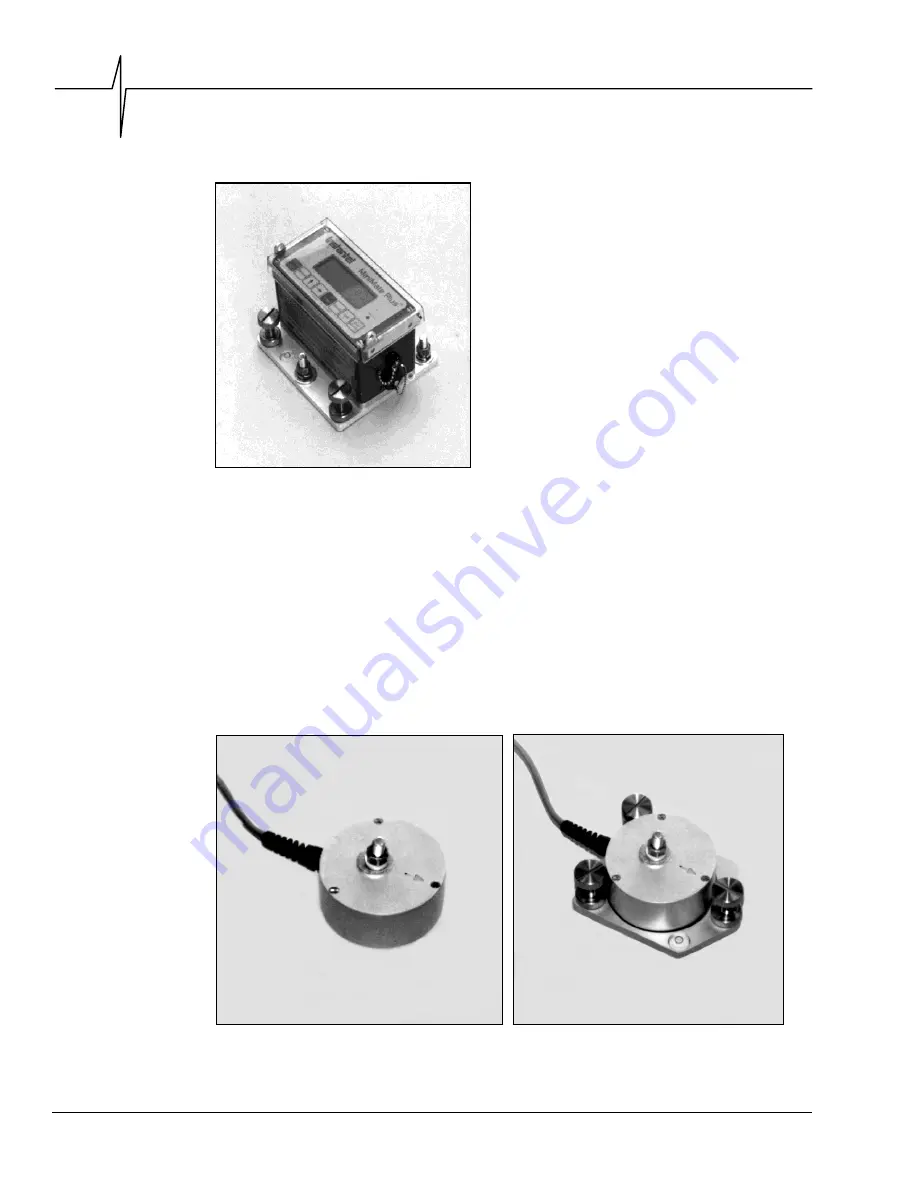
a.  Bolting the MiniMate Plus  

Use the optional fastening plate to bolt the MiniMate 
Plus to a hard surface. The fastening plate has three 
leveling feet and an integrated bubble level. Attach 
the leveling plate to the MiniMate Plus with the three 
screws provided. Use 3/8 inch (9.5 mm) bolts or 
threaded rods to bolt the MiniMate Plus to a surface. 
Place the unit on the surface and mark the position of 
the three bolts. Install the bolts according to the 
manufacturer’s instructions. Slide the MiniMate Plus 
and fastening plate over the bolts. Slide a 3/8 inch 
(9.5 mm) washer and a 3/8 inch (9.5 mm) lock washer 
over each bolt. Level the MiniMate Plus using the 
leveling feet and integrated bubble level. Tighten the 
retaining nuts to finish the installation. Press the 

Test


key to check your sensors using Sensorcheck. 

WARNING

: Do not over-tighten the screws when 

attaching the MiniMate Plus to the leveling plate. 
This can damage the casing of the MiniMate Plus. 


b.  Bolting the Standard Transducer 

A standard transducer may be bolted to a surface alone or with the aid of the optional leveling 
plate. Position the standard transducer with leveling plate, if attached, on the surface and mark the 
position of the bolt. Use a 3/8 inch (9.5 mm) bolt or threaded rod. Install the bolt according to the 
manufacturer’s instructions. Slide the standard transducer, and leveling plate, over the bolt. Slide a 
3/8 inch (9.5 mm) washer and a 3/8 inch (9.5 mm) lock washer over the bolt. If using the leveling 
plate, level the standard transducer using the leveling feet and integrated bubble level. Tighten the 
retaining nut to finish the installation. Press the 

Test

 key to check your sensors using 

Sensorcheck. 


Figure 3.11 Bolting the Standard 


Figure 3.12 Bolting the Standard Transducer 

Transducer to a Surface. 


to a Surface using the Leveling Plate. 

Figure 3.10 Bolting the MiniMate Plus to a 
Surface using the Fastening Plate. 

Содержание 716A0401

Страница 1: ......

Страница 2: ...tantel cannot accept responsibility for the results unless it has entered into a contract for services which clearly define such an extension of responsibility and liability Any shipments returned dir...

Страница 3: ...1 3 1 What is Event Monitoring 3 1 3 2 Eight Channel Models 3 2 3 3 Installing the MiniMate Plus or the Standard Transducer 3 2 3 3 1 Soft Surface Installation 3 3 3 3 2 Hard Surface Installation 3 5...

Страница 4: ...Key 3 19 3 10 1 View Events 3 19 3 10 2 Delete All Events 3 20 3 10 3 Print Event List 3 21 3 10 4 Print Selected Event 3 21 3 10 5 Print All Events 3 21 3 10 6 Upload One Event 3 21 3 10 7 Upload All...

Страница 5: ...Analysis Techniques 5 9 5 5 1 Ground Vibrations 5 9 5 5 2 Sound Pressure 5 12 5 6 Alternate Manual Waveform Calculations 5 13 5 6 1 Sinusoidal Waveforms 5 13 5 6 2 Nearly Triangular Waveforms 5 14 5...

Страница 6: ...iv MiniMate Plus Operator Manual Notes...

Страница 7: ...al information See the BlastWare III Operator Manual for installation instructions Check the Package Contents Please check that you received all the parts identified on your shipping invoice Remember...

Страница 8: ...being careful not to over tighten or pinch wires WARNING Do not pull on the internal wires or allow them to be pinched and damaged when assembling the monitor MINIMATE PLUS Battery Top Cover Figure 1...

Страница 9: ...el offers the most comprehensive Product Support Program available You receive a two year warranty product support and product updates your monitor and sensors must be returned to Instantel for annual...

Страница 10: ...MiniMate Plus and Transducers The geophones inside the MiniMate Plus models with an internal transducer and external transducers contain magnets that could erase the data stored on computer disks Cle...

Страница 11: ...the MiniMate Plus keys you press For example when you see Setups key it means press the Setups key located on the MiniMate Plus keyboard Window This word when capitalized refers to a message window ap...

Страница 12: ...x MiniMate Plus Operator Manual Notes...

Страница 13: ...al to record your first event quickly and easily This section describes basic functions with illustrative examples to lead you through The following section called the Compliance Module covers the ope...

Страница 14: ...k displacement National Frequency Analysis Standards many national frequency analysis standards come with the MiniMate Plus Future standards can be programmed into the monitor as they are implemented...

Страница 15: ...niMate Plus to a wall or ceiling as well as ground installations Transducer Leveling Plate with adjustable leveling feet and integrated bubble level Used to mount the transducer to a wall or ceiling a...

Страница 16: ...Chapter 1 1 4 MiniMate Plus Operator Manual 1 4 MiniMate Plus Keys...

Страница 17: ...he transducer in the direction of the event For this tutorial point it away from yourself Press on the MiniMate Plus s protective cover or transducer to force the ground spikes fully into the ground C...

Страница 18: ...sorcheck program and tests the transducer and microphone The message All Channels Working Press Option Test to Review Setups appearing on the display tells you that your installation is level Step 4 R...

Страница 19: ...ight Arrow key to move the cursor and the Up Arrow key to change the trigger level number Press the Enter key to save your setting The Mic Trigger Level Window appears Set the Linear Mic trigger level...

Страница 20: ...MiniMate Plus then returns to the monitoring mode ready to record another event Now bump the MiniMate Plus or the transducer Again the MiniMate Plus beeps The results appear on the display and the Min...

Страница 21: ...itate particles in a side to side motion Vertical ground vibrations agitate particles in an up and down motion Longitudinal ground vibrations agitate particles in a forward and back motion progressing...

Страница 22: ...nstallation methods For wall and ceiling installations refer to the Reference chapter Other methods may be used if they satisfy the following requirements 1 Arrow Pointed in Direction of the Event The...

Страница 23: ...sing the Ground Spikes Screw the three ground spikes into the bottom of the MiniMate Plus or the standard transducer and tighten Aim the MiniMate Plus or the standard transducer in the direction of th...

Страница 24: ...re no water is expected The ground must be hard and compact with no loose material between the MiniMate Plus or the standard transducer and the compact ground material Dig a hole from four inches 10 c...

Страница 25: ...g the Standard Figure 3 9 Fill In and Pack the Material Transducer around the Standard Transducer 3 3 2 Hard Surface Installation For hard surface installations such as rock concrete or solid ice the...

Страница 26: ...over tighten the screws when attaching the MiniMate Plus to the leveling plate This can damage the casing of the MiniMate Plus b Bolting the Standard Transducer A standard transducer may be bolted to...

Страница 27: ...material impact on results WARNING Handle the microphone with care Dropping the microphone or otherwise subjecting it to impact may damage the microphone element The windscreen can help to protect th...

Страница 28: ...e the setups using the MiniMate Plus keyboard For information on how to change the setups using a personal computer refer to the BlastWare III operator manual 3 8 1 Record Mode A record mode determine...

Страница 29: ...ess 2048 samples per second b more than 4 channels 1024 samples per second Note Histogram Combo record mode consumes more battery power than the Single Shot Continuous or Manual recording modes We rec...

Страница 30: ...a range when it appears on the display On eight channel monitors set the Maximum Geo Range for the first four channels then set the Maximum Geo2 Range for channels five to eight 3 8 5 Trigger Source...

Страница 31: ...l record modes The record stop mode sets how the MiniMate Plus stops recording after being triggered You can choose between a Fixed setting or an Auto setting Fixed sets the record time to a specified...

Страница 32: ...ire event The following table lists approximate recording times for the various histogram intervals The table assumes 300 event 960 kB available memory and sufficient power supplied to the monitor dur...

Страница 33: ...cord with an event leaving you space to manually write in notes after you have printed the event 3 8 11 Job Number Format You may include a job number for each recorded event Job numbers help you keep...

Страница 34: ...on must be activated in order for the time to be corrected The time is adjusted as part of the Daily Self Check Please see page 3 15 for information on how to activate the Daily Self Check 3 8 14 Date...

Страница 35: ...key to change the hour and minute settings Press the Enter key to save your start time The Daily Stop Time Window appears Use the Right Arrow key to move the cursor and the Up Arrow key to change the...

Страница 36: ...the Setups key at the same time when the Main Window is displayed Press the Enter key to scroll through the windows until the Measurement System Window appears Press the Right Arrow key to display the...

Страница 37: ...ey together Press the Enter key to scroll the windows until the Microphone Units Window appears Press Right Arrow key repeatedly to display the three choices Press the Enter key to select a measuremen...

Страница 38: ...e monitor to match the baud rate of your computer or modem To choose the serial connection press the Right Arrow key and the Setups key together Press the Enter key to scroll the windows until the Ser...

Страница 39: ...Now and then enters monitor mode 4 Set GSM Signal Strength This setting is used to test the signal strength of GSM cellular modems Press the Enter key to display signal strength from the modem and the...

Страница 40: ...t appears only Frequency is not calculated for advanced events W Jan 25 99 10 17 47 1 2 91 mm s 32 Hz 2 3 78 mm s 37 Hz previous next PPV and Frequency Channels 3 Acceleration and peak displacement re...

Страница 41: ...y when the Main Window is displayed until the Print Selected Event Window appears Press the Enter key to display the most recently recorded event Press the Up or Right Arrow keys to scroll through the...

Страница 42: ...tors To upload all the events press the Up Arrow key when the Main Window is displayed until the Upload All Events Window appears Press the Enter key to select this choice The message Uploading along...

Страница 43: ...iginal factory defaults If you choose to reset the monitor all of your setups will lost and replaced with the factory defaults You can reprogram your setups again anytime you want WARNING Resetting th...

Страница 44: ...continuous record mode Set a fixed record time The auxiliary trigger does not operate in the auto record time setting Press the Option key and the Setups key together when the Main Window is displaye...

Страница 45: ...the Enter key to scroll through the windows until the Trigger sample width Window appears Use the Up Arrow key to change the setting Press the Enter key to save your setting i Cut Cable Detection This...

Страница 46: ...s Operator Manual 3 13 6 Option Key Right Arrow Key Left Arrow These keys when pressed together act as a left arrow 3 14 Right Arrow Key The Right Arrow key scrolls through windows and moves the curso...

Страница 47: ...e following menu item in the advanced mode 4 1 1 Instrument Mode The instrument mode displays the current operating mode of the monitor The mode can be changed between the compliance and the advanced...

Страница 48: ...ble available available 4096 available available available available 2048 available available available available 1024 available available available available 512 available available available availab...

Страница 49: ...the Setups key when the Main Window is displayed Press the Enter key to display the Trigger Level Ch Window appears Use the Right Arrow key to move the cursor and the Up Arrow key to change the trigge...

Страница 50: ...s serial connection and baud rate The timer mode serial connection and baud rate operate the same in the advanced mode as they do in the compliance mode Please refer to page 3 14 in Compliance Module...

Страница 51: ...simple procedure requiring no special tools To switch the vertical and transverse geophones remove the four screws on the top cover Remove the top cover to expose the geophones Switch the vertical and...

Страница 52: ...on the side of the transducer and pry off the top cover Remove the two screws securing the electronics to expose two geophones Switch the vertical and the transverse geophones Replace the electronics...

Страница 53: ...the three screws provided Slide the standard transducer over the bolt with the arrow pointed in the direction of the event Slide a 3 8 inch 9 5 mm washer and a 3 8 inch 9 5 mm lock washer over the bol...

Страница 54: ...ng Secure the leveling plate to the MiniMate Plus with the three screws provided Place the assembly on the ceiling with the arrow pointing in the direction of the event Mark the position of the three...

Страница 55: ...h the transducer over the bolt Slide a 3 8 inch 9 5 mm washer and a 3 8 inch 9 5 mm lock washer over the bolt Screw on the retaining nut to hold the unit in position Level the assembly by adjusting th...

Страница 56: ...e particles of the surrounding terrain The coil because of its inertia does not move and the resulting magnet versus coil motion induces a voltage which is proportional to particle velocity b Instante...

Страница 57: ...ors In the first stage the program displays the MiniMate Plus serial number software version the total amount of memory installed in the MiniMate Plus the total amount of memory available to store eve...

Страница 58: ...rom 2 8 to 4 8 The figure below displays a graph of a geophone coil s free fall response A1 and A2 are used for overswing calculations Figure 5 10 Calculating a Geophone s Overswing Ratio 5 3 2 Checki...

Страница 59: ...f the transverse vertical and longitudinal axes The MiniMate Plus calculates Peak Vector Sum using data from all three axes a Peak Particle Velocity PPV Peak Particle Velocity indicates the maximum sp...

Страница 60: ...re above the zero crossing frequency uses the 1 2 period indicated by T1 In the figure below the zero crossing frequency uses the 1 2 period indicated by T2 Notice that T1 is less than T2 because of t...

Страница 61: ...acceptable window Whenever a frequency cannot be calculated the message 1 Hz displays The message N A indicates an entire waveform was not captured and therefore no frequency could be calculated More...

Страница 62: ...nd is calculated by squaring and adding the magnitudes and taking the square root PVS T2 V2 L2 where T particle velocity along the transverse plane V particle velocity along the vertical plane L parti...

Страница 63: ...on the shape of the waveform being analyzed A complete discussion of the procedures is beyond the scope of this manual Two useful reference texts are G A BOLLIGER BLAST VIBRATION ANALYSIS Southern Il...

Страница 64: ...ation mm s2 2 T Am 5 6 2 Nearly Triangular Waveforms Motion is irregular and has large amplitude Figure 5 16 Manual Waveform Calculations on Nearly Triangular Waveforms a Calculating Displacement Maxi...

Страница 65: ...Manual Waveform Calculations on Compound Waveforms a Calculating Displacement Maximum Displacement in T 2 A T 2 A 1 1 2 2 Maximum Displacement mm T 2 A T 2 A 1 1m 2 2m b Calculating Acceleration Maxi...

Страница 66: ...Chapter 5 5 16 MiniMate Plus Operator Manual Notes...

Страница 67: ...VAC 60 Hz electrical outlet The battery charging indicator light turns on For electrical outlets other than 120 VAC 60 Hz you must use an optional power converter see your dealer for more information...

Страница 68: ...one sensors located inside the MiniMate Plus or inside the Standard Transducer and the microphone require annual calibration to ensure continued accurate monitoring results Calibration may be performe...

Страница 69: ...tor fails to trigger and record an event The monitor is not in monitor mode Press the Start Monitor key to enter monitor mode Trigger Level set too high Lower Trigger Level The monitor triggers Trigge...

Страница 70: ...tions and cables Transducer installed upside down Check the transducer for the arrow on the top Ceiling Installation Vertical geophone not inverted Invert the vertical geophone Damaged transducer Have...

Страница 71: ...Appendix MiniMate Plus Operator Manual A 1 Appendix...

Страница 72: ...Appendix A 2 MiniMate Plus Operator Manual...

Страница 73: ...00 sec Days Storage 2 8 or 14 days at 5 second interval 34 or 170 days at 1 minute interval HistogramRecordMethod Recordtomemory and orinternalprinter Programinterval2 5 15 60 300or900sec Histogram Da...

Страница 74: ...ccessories contact your dealer or Instantel 338B34 MiniMate Plus Fastening Plate with leveling feet and integrated level 715A1601 Transducer Leveling Plate with leveling feet and integrated level 714A...

Страница 75: ...rts also called National Frequency Analysis Standards including U S A USBM OSMRE British Standard BS 6472 French GFEE German DIN 4150 New Zealand 4403 1976 and Spain UNE 22 381 Two frequency standards...

Страница 76: ...power supply Aggregate Sample Rate The aggregate sample rate sample rate x the number of recording channels measures the effect of choosing combinations of sample rates and recording channels The foll...

Страница 77: ...320 printer Other printer types may work with the MiniMate Plus if they can be configured to the settings listed in the tables below The diagram below illustrates how to connect the printers to a Min...

Страница 78: ...ure the Printer You must configure the printer to work with your MiniMate Plus Follow the instructions in your printer s user s manual Configure the printer to the settings appearing at the end of thi...

Страница 79: ...the following Printer Set Up Parameters 1 Emulation FX 85 2 Page Length 11 inches 3 Perforation Skip Off 4 Character Set USA 5 Character Default Set 1 6 Carriage Return CR 7 Line Feed LF CR 8 Graphic...

Страница 80: ...g Epson LQ Mode Settings 1 Horizontal Print Position OFF 2 Not Used 3 Text scale mode OFF 4 5 Top Margin OFF 6 Smoothing mode OFF 7 Automatic Power Off Any setting 8 Font Typeface lock mode OFF 9 Inpu...

Страница 81: ...Appendix MiniMate Plus Operator Manual A 11 Notes...

Страница 82: ...Appendix A 12 MiniMate Plus Operator Manual...

Страница 83: ...3 25 power saving timeout to conserve battery power 3 24 turn backlight off to conserve power 3 24 Baudrate direct or modem 3 18 Beep When Triggered 3 19 Bolting MiniMate Plus or Transducer 3 6 Buryi...

Страница 84: ...on key Enter key 3 25 Histogram Strip chart record mode 3 8 Histogram combo record mode 3 9 Histogram interval 3 12 HP DeskJet 320 A 9 I Identification Numbers v Imperial 3 16 Installation bolting 3 5...

Страница 85: ...Key Left Arrow 3 26 Option Key Setups Key advanced module 4 1 compliance module 3 23 Option Key Test Key Review Setups 3 25 Option Key Up Arrow Key Down Arrow 3 25 Overswing Ratio 5 8 P Parts A 4 Pass...

Страница 86: ...calibration requirements 5 7 ceiling installation 5 4 extension cable 1 3 hard surface installation 3 5 installation 3 2 installing using the ground spikes 3 3 Instantel Standard Transducer 5 6 levell...

Отзывы: