TITAN GO Product Manual |
Wiring and Connections
INGENIA | 2022-07-14 08:35:14
73
6.
7.
If the installation allows this connect the motor housing to the main supply negative (GND). Only do so if an
experienced electrician with perfect understanding of the installation and system knows that this is correct.
When no error appear with motor turning and active (orange and blue leds always off). You can proceed and
configure commutation sensor. After that configure the control loops, starting with the current loop.
7.5.6 Digital input feedback - PWM encoder
Titan Go Servo Drive can also use a PWM encoder connected through the Communications and IOs connector as a
feedback element. A PWM encoder provides a Pulse Width Modulated (PWM) signal with a duty cycle proportional to
the angle (position) of the rotor. This feedback can be interfaced through the high-speed digital input 1 (
HS_GPI1
).
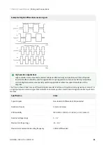
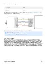
Only single ended encoders can be used. Further specifications about the PWM input can be found in
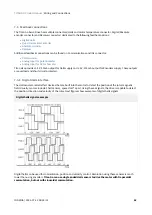
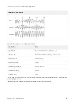
Next figure illustrates PWM feedback input for different rotor positions:
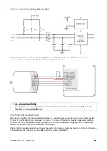
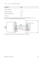
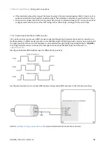
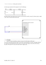
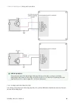
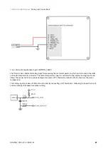
Next figures illustrates how to connect differential and single ended PWM encoders to the Titan Go Servo Drive:
Содержание Titan GO
Страница 19: ...TITAN GO Product Manual Product Description INGENIA 2022 07 14 08 35 14 19 ...
Страница 56: ...TITAN GO Product Manual Wiring and Connections INGENIA 2022 07 14 08 35 14 56 ...
Страница 89: ...TITAN GO Product Manual Wiring and Connections INGENIA 2022 07 14 08 35 14 89 ...
Страница 101: ...TITAN GO Product Manual Wiring and Connections INGENIA 2022 07 14 08 35 14 101 ...


