background image

TITAN GO Product Manual | 

Wiring and Connections

INGENIA | 2022-07-14 08:35:14

99

7.9.3  STO abnormal operation

Abnormal operation of the STO is when only one of the channels is energised.

 In case that only one channel is 

energised for more than 1.6 s, a dangerous failure in the system is considered and the STO is activated in latching 

mode. The fault cannot be reset until a supply reset is performed. 

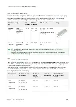
The following figure shows an example of the STO abnormal operation. 

The following table shows a sumary of the STO performance.

Содержание Titan GO

Страница 1: ...INGENIA CAT S L C ÁVILA 124 2ºB 08018 BARCELONA TITAN GO Product Manual Edition 2022 07 14 08 35 14 For the most up to date information visit the online manual ...

Страница 2: ...chitecture 17 4 4 1 Power stage and supply architecture 18 5 Connectors Guide 20 5 1 Supply shunt and motor terminals 20 5 2 Ring terminals and screws 22 5 3 Micro Fit 3 0 connectors mating 23 5 4 P1 Aux supply connector 24 5 5 P2 Communications and IOs connector 26 5 6 P3 Safe torque off connector 29 5 7 P4 Digital halls and motor temperature connector 30 5 8 P5 USB connector 32 5 9 P6 Encoder co...

Страница 3: ... 7 4 3 1 Wire section 59 7 4 3 2 Motor choke 59 7 4 3 3 Wire length 60 7 4 4 Shunt braking resistor 60 7 5 Feedback connections 62 7 5 1 Digital Halls interface 62 7 5 2 Digital Incremental Encoder 64 7 5 3 Absolute encoder interface 66 7 5 4 Analog encoder Sin Cos encoder interface 68 7 5 5 Resolver interface 70 7 5 5 1 Resolver Gain 72 7 5 5 2 Configuring the resolver 72 7 5 6 Digital input feed...

Страница 4: ...ndations 90 7 8 2 RS485 interface 91 7 8 2 1 Multi point connection using daisy chain 92 7 8 3 CANopen interface 93 7 8 3 1 CAN interface for PC 95 7 8 3 2 CAN wiring recommendations 96 7 9 Safe Torque Off STO 97 7 9 1 Fully independent STO channels 98 7 9 2 STO status feedback output 98 7 9 3 STO abnormal operation 99 8 Dimensions and assembly 102 8 1 Titan Go Dimensions 102 8 2 Assembly Instruct...

Страница 5: ...ormation is supplied solely for the purpose of assisting users of the product in its installation INGENIA CAT S L rejects all liability for errors or omissions in the information or the product or in other documents mentioned in this document The text and graphics included in this document are for the purpose of illustration and reference only The specifications on which they are based are subject...

Страница 6: ...configuration or setup with unlimited current settings Disconnect the Titan Servo Drive from all power sources before proceeding with any possible wiring change After turning off the power and disconnecting the equipment power source wait at least 20 seconds before touching any parts of the controller that are electrically charged or might be hot 3 3 Precautions The following statements should be ...

Страница 7: ...lmost any feedback sensor including absolute serial encoders and resolvers Its design includes multiple communication ports as CANopen RS 485 USB all of them are electrically isolated The Titan Go Servo Drive has been designed with efficiency in mind It incorporates cutting edge power semiconductor technology as well as optimized control algorithms to provide the perfect trade off between electrom...

Страница 8: ... DC bus capacitance 63 µF 224 µF if CCMO version is chosen Minimum motor inductance 50 µH for low inductance motors use high PWM frequency mode 50 µH Nominal phase continuous current BLDC mode 150 ARMS with heatsink 65 ARMS with heatsink Nominal phase continuous current DC mode 150 ADC 65 ADC Maximum phase peak current 250 ADC 1 s 85 ADC 1 s Current sense range 457 A Versions 1 0 0 and 1 1 0 359 A...

Страница 9: ...ary brushless trapezoidal and sinusoidal Linear brushless trapezoidal and sinusoidal DC brushed Rotary voice coil Linear voice coil Power stage PWM frequency 10 kHz default 20 kHz alternative PWM frequency configurable preferred for low inductance motors Current sensing Isolated current sense on phases A B and C Accuracy is 2 full scale 10 bit ADC resolution Sensors for commutation brushless motor...

Страница 10: ...and Contact Ingenia Input differential resistance 24 kΩ Inputs outputs and protections General purpose Inputs and outputs 5 x isolated single ended digital inputs GPI1 GPI2 GPI3 HS_GPI1 HS_GPI2 5 V TTL logic 1 x isolated 10 V differential analog input 12 bits AN_IN1 1 x isolated digital output GPO1 3 3V logic Dedicated Inputs and outputs 2 x isolated Safe Torque Off inputs 24V level 1 x isolated S...

Страница 11: ... feedback reaction 1 ms Pulses 1 ms can be used for safety PLCs but will be ignored Pulses between 14 ms and 1 ms can be used for self test Motor Brake Not available Communications USB MiniUSB 2 0 vertical connector Fully isolated 2 5 kVRMS 1 min Serial RS 485 full duplex compatible with RS 422 isolated 2 5 kVRMS Default 115200 bps 8 data bits no parity 1 stop bit no flux control 120 Ω termination...

Страница 12: ...1H1 1 1 0 i047 01H2 1 1 0 i047 01H3 1 1 0 First product release Changes from the previous version Modifications on the aluminum cooling plate reduction of 1 mm thickness and added extra PCB support area for better vibration and thermal performance Added 2 5 kV isolation to USB ports The drive is no longer powered from USB but communication reliability is greatly enhanced Change high voltage notifi...

Страница 13: ...h USB connected Removed Safe Torque Off error at power up that caused the reset Improvement of overcurrent performance Improvement on EMI of the power stage Manufacturing improvements 4 3 Power and current ratings TTN x xx C C variants of Titan Go are capable of providing the nominal current from 40 ºC to 85 ºC temperature measured in the cold plate with a 0 1 ºC W heatsink Fischer LA 11 200 24 at...

Страница 14: ...rtional ratio PWM switching frequency similar to DC bus voltage the PWM switching frequency directly affects the commutation losses Typically 10 kHz is the default value to reduce these losses but it can be increased up to 20 kHz Other less relevant parameters affect also the power losses but are not considered in the following graphs Air temperature higher power semiconductor temperatures reduce ...

Страница 15: ... Notes Maximum absolute power stage temperature 110 ºC Measured on the PCB not the heatsink and accessible via register Thermal resistance from power stage to the heatsink 0 01 7 ºC W Does not consider the thermal resistance of the heatsink but assumes the cold plate is a thermal conductor not the thermal dissipator Thermal resistance from power stage to air 5 ºC W Considering the drive is vertica...

Страница 16: ...n with a heatsink A heatsink is needed to reach the nominal current at any ambient temperatures When using high efficiency heatsinks or in enclosed spaces the equation can be simplified as follows Current derating The current derating graph is only indicative and is based on thermal tests performed in a climatic chamber where there was enough room for natural air convection Each application may re...

Страница 17: ...n by ensuring 10 mm air space around the drive Use a good thermal interface material to improve the heat dissipation See Dimensions and assembly for details If housed use a good thermal conductivity material such as black anodized aluminum Placing the drive in a small plastic package will definitively reduce its temperature range Temperature range can be increased by providing forced cooling with ...

Страница 18: ... 14 08 35 14 18 4 4 1 Power stage and supply architecture The following drawing shows the architecture of the power stage and its main components Also it clarifies how the internal power supplies are wired For simplicity power transistors are shown as switches ...

Страница 19: ...TITAN GO Product Manual Product Description INGENIA 2022 07 14 08 35 14 19 ...

Страница 20: ... GO Product Manual Connectors Guide INGENIA 2022 07 14 08 35 14 20 5 Connectors Guide This chapter details the Titan Go Servo Drive connectors and pinout 5 1 Supply shunt and motor terminals Power terminals ...

Страница 21: ... Shunt braking transistor output Shunt braking resistor should be connected between POW_SUP and SHUNT_OUT 5 GND_P Power ground connection Isolated from logic GND and Protective Earth 6 POW_SUP Power supply positive 7 9 DC_BUS Internal DC bus negative Internally connected to GND_P but not intended as power supply terminal Used for additional DC link capacitance M3 8 10 DC_BUS Internal DC bus positi...

Страница 22: ...minals Following are shown the recommended part numbers M8 screw Assembly Description M8 allen screw 12 mm length The following picture shows the correct order of the mechanical elements and extra comments for the assembly Extra capacitance It is recommended to add extra capacitance to the main DC supply The Titan Go has minimal DC bus capacitance that is enough to filter high frequency currents a...

Страница 23: ...G cable Part number Molex 0190710285 Distributor codes Digi Key WM13727 ND Mouser 538 19071 0285 Brass washer Description M8 brass washer Part number RS Pro 483 2637 Distributor codes RS 483 2637 5 3 Micro Fit 3 0 connectors mating All Titan Go Servo Drive signal and communication connections are based in Molex Micro Fit 3 mm pitch connectors Multi core crimped cables can be used for wiring inputs...

Страница 24: ...mbled wires Description 20 24 AWG pre crimped jumper cable 50 8 mm Note there are many lengths and colors available at Digi Key Image 5 4 P1 Aux supply connector Titan GO is self supplied from the DC bus using an internal DC DC converter that starts at 60 V and works up to 850 V However some applications require an independent auxiliary power supply to work with the power off This can be done with...

Страница 25: ...D_P 2 24V_IN 24 V logic supply input 10 V to 60 V 3 GND_D Logic ground connection isolated from GND_P 4 24V_OUT 24 V logic auxiliar supply output Notes The internal logic supply can be monitored using the analog input 2 MOLEX Micro Fit connectors do not follow the typical pinout layout of other connectors such as pin headers or ribbon connectors Pay close attention not to connect them in a wrong o...

Страница 26: ...Distributor code Digi Key WM1784 ND Mouser 538 43025 0400 Farnell 672890 Notes See Micro Fit 3 0 connectors mating for further information about crimping terminals and cables 5 5 P2 Communications and IOs connector Titan GO has an isolated connector for the communications and the inputs outputs It includes RS 485 CAN 5x Digital inputs 1x Digital output and 1x Analog input P2 connector ...

Страница 27: ... to master TX 2 RS485_RX RS485 receive data should be connected to master TX 3 CAN_L CAN bus line dominant low 4 CAN_H CAN bus line dominant high 5 GND_ISO Ground for the isolated connector 6 AN_IN Differential 10 V analog non inverting input Single ended analog input 7 GPI2 General purpose single ended digital input 2 8 5V_ISO 5 V 50 mA max 9 GND_ISO Ground for the isolated connector ...

Страница 28: ... V analog inverting input Single ended analog input ground 16 HS_GPI1 High speed digital single ended input 1 Command source Pulse input Feedbacks PWM input 17 GPI3 General purpose single ended digital input 3 18 HS_GPI2 High speed digital single ended input 2 Command source Direction input Notes GPO1 is 0 to 3 3 V with a 330 Ω resistor in series for current limiting P2 Mating Description 3 00mm P...

Страница 29: ...tor Titan GO has a Safe Torque Off interface SIL 3 compliant P3 connector 6 pin 2 row Micro Fit 3 0 3 mm pitch header Molex Pin Signal Function 1 STO1 Safe Torque Off input 1 24 V levels 2 STO2 Safe Torque Off input 2 24 V levels 3 STO_STATUS_EMITTER Safe Torque Off Feedback output signalling optocoupler emitter 4 NC Not connected 5 STO_COMMON Safe Torque Off input common optocoupler LEDs cathode ...

Страница 30: ...urrent sense amplifiers It is not possible to read motor phase current with this error active P3 Mating Description 3 00mm Pitch Micro Fit 3 0 Receptacle Housing 6 Circuits Image Part number Molex 43025 0600 Distributor code Digi Key WM1785 ND Mouser 538 43025 0600 Farnell 672907 Notes See Micro Fit 3 0 connectors mating for further information about crimping terminals and cables 5 7 P4 Digital ha...

Страница 31: ...ection isolated from GND_P and GND_D to maximize noise immunity 7 MOT_TEMP1 Motor temperature sensor connection connect the other terminal to pin 8 Includes a 30 kΩ pull up to 3 3 V The pin is connected to analog input 3 8 MOT_TEMP2 Motor temperature sensor return a 330 Ω connects this pin to digital GND Notes P4 Mating Description 3 00mm Pitch Micro Fit 3 0 Receptacle Housing 8 Circuits Image ...

Страница 32: ...25 0800 Farnell 672919 Notes See Micro Fit 3 0 connectors mating for further information about crimping terminals and cables 5 8 P5 USB connector P5 connector 5 pin vertical mini USB connector Wurth Electronics 651005136421 Pin Signal Function 1 USB_SUPPLY USB 5V Does not supply the Titan 2 USB_D USB Data line 3 USB_D USB Data line 4 NC Not connected ...

Страница 33: ... downloading latest firmware revision Shorter USB cables are preferred whenever possible for minimal EMI Please see Communications page for further information The Titan USB port is 100 isolated from the power P5 Mating Description USB Shielded I O Cable Assembly USB A to Mini USB B 1 m Length Black Lead Free Not included in the delivery of Titan Go Image Part number Molex 43025 0800 Distributor c...

Страница 34: ...1 3 8 GND_D Logic ground 2 QEA SIN_P Quadrature A positive input Sin positive input 4 QEB COS_P Quadrature B positive input Cos positive input 5 QEZ REF_P Index positive input Reference positive input 6 5V_OUT 5 V 200 mA regulated and short circuit protected power supply for the encoder 7 QEA SIN_N Quadrature A negative input Sin negative input 9 QEB COS_N Quadrature B negative input Cos negative ...

Страница 35: ...encoder as incremental before doing connecting it to prevent signal collision between clock output and A signals input P6 Mating Description 3 00mm Pitch Micro Fit 3 0 Receptacle Housing 10 Circuits Image Part number Molex 43025 1000 Distributor code Digi Key WM1787 ND Mouser 538 43025 1000 Farnell 672920 Notes See Micro Fit 3 0 connectors mating for further information about crimping terminals an...

Страница 36: ...tion for incremental encoder 1 EXC Excitation positive 2 COS Cosine positive 3 SIN Sine positive 4 EXC Excitation negative 5 COS Cosine negative 6 SIN Sine negative Notes Attention this connector is the same model as the STO Titan standard option is for resolver with a transform ratio of 1 0 5 Other gains are possible on demand P7 Mating ...

Страница 37: ...s Image Part number Molex 43025 0600 Distributor code Digi Key WM1785 ND Mouser 538 43025 0600 Farnell 672907 Notes See Micro Fit 3 0 connectors mating for further information about crimping terminals and cables 5 11 P8 Absolute Encoder P8 connector 6 pin 2 row Micro Fit 3 0 3 mm pitch header Molex Pin Signal Function for absolute encoder ...

Страница 38: ...lock negative signal output 8 GND_D Logic ground 9 DIN Data negative signal input 10 NC Not connected Notes This connector was added on version 1 2 0 Wiring is 100 compatible with connectors of version 1 1 0 P8 Mating Description 3 00mm Pitch Micro Fit 3 0 Receptacle Housing 10 Circuits Image Part number Molex 43025 1000 Distributor code Digi Key WM1787 ND Mouser 538 43025 1000 Farnell 672920 Note...

Страница 39: ...ve provides information through 6 signaling LEDs Supply and operation 2 LEDs below the Titan Go logo Shunt resistor activation 1 LED below the Titan Go logo CANopen communication 2 LEDs below the Titan Go logo High voltage 1 LED near the AUX Supply connector Resolver Status 2 LEDs Near the Resolver connector ...

Страница 40: ...TITAN GO Product Manual Signalling LEDs INGENIA 2022 07 14 08 35 14 40 6 1 Power and operation signalling LEDs Three LEDs placed below the Titan Go GO logo indicate the supply and operation status ...

Страница 41: ...CiA 303 3 recommendations The red LED is ERROR LED and green one is RUN LED ERROR LED indicates the status of the CAN physical layer and errors due to missed CAN messages sync guard or heartbeat Next table the meaning of the ERROR LED states ERROR LED state Concept Description Off No error Device is in working condition Single flash Warning limit reached At least one of the error counters of the C...

Страница 42: ... short flashes 200 ms separated by an off phase 200 ms The sequence is finished by a long off phase 1000 ms Triple flash Sequence of 3 short flashes 200 ms separated by an off phase 200 ms The sequence is finished by a long off phase 1000 ms Blinking On and off with a frequency of 2 5 Hz ON for 200 ms followed by off for 200 ms Note that the specified timings can vary in up to 20 6 3 Resolver stat...

Страница 43: ... sine and cosine at their maximum Too much amplitude or too low causes a degradation of read signal Trick The gain can be changed by sliding the resolver rotor inwards or outwards relative to the stator Z axis This changes the reluctance and affects the transform ratio Enable the motor in open loop vector mode no current loop no position or velocity loop Set frequency to 1 Hz or lower and start in...

Страница 44: ...for ensuring safe immune and optimal servo performance of Titan Go Servo Drive Please be sure to follow this detailed recommendations on connection and check the technical details of each interface Protective earth Power supply DC bus bulk capacitance Motor and shunt braking resistor Feedback connections I O connections Command sources Communications Safe Torque Off STO ...

Страница 45: ...ugh safety capacitors This provides a low impedance preferential path for coupled common mode noises that otherwise would be coupled to sensitive electronics like the encoders A good grounding of the drive to the earth of the power supply is also essential for EMI reduction Titan Go Servo Drive provides the following earth ground connection points which are internally connected and decoupled to po...

Страница 46: ...ls connect all PE terminals in a central connection bus Whenever possible mount the Ingenia drive on a metallic conductive surface connected to earth Use good quality plated screws that won t oxidize or lose conductivity during the expected lifetime Note that the PE terminal is internally connected with the Titan Go Servo Drive standoffs For achieving low impedance connections use wires that are s...

Страница 47: ...ct Manual Wiring and Connections INGENIA 2022 07 14 08 35 14 47 Description Image Part number Cable Clamp Aluminum 31 75 mm Essentra components AL20 Cable Clamp with Bolt Type Stainless Steel 76 mm Panduit Corp PCD7B ...

Страница 48: ...at the current rating for the power supply is at least as high as the motor The voltage and current range can be decreased due to the motor requirements Further information on how to dimension a power supply for the Ingenia drives can be found here 7 2 2 Power supply connection Titan Go power and logic supply are provided through the same terminal However the Aux supply connector can be used to su...

Страница 49: ...wer supply voltage is 60 V if single supply is used Isolated power supplies For safety reasons it is important to use power supplies with full galvanic isolation Maximum power supply voltage Please note that the maximum nominal power supply voltage is different for each version of the Titan Go Up to 200 V for TTN xx 200 C C Up to 400 V for TTN xx 400 C C Up to 800 V for TTN xx 800 C C Do not suppl...

Страница 50: ...internal diode connects to the internal 24 V logic supply Note that the minimum power supply voltage is 10 V if dual supply is used Next figure shows a simplified wiring diagram for the Titan Go Servo Drive supplied from two batteries Note that the minimum power supply voltage is 10 V if dual supply is used Motor braking can cause reverse current sense and charge the battery Always ensure that the...

Страница 51: ...m in star topology for reducing cable impedance and common mode coupled noise That is connect each drive to the common supply using separate wires for positive and return Maximum power supply voltage Please note that the maximum power supply voltage is different for each version of the Titan Go Up to 200 V for TTN xx 200 C C Up to 400 V for TTN xx 400 C C Do not supply a higher voltage as the Tita...

Страница 52: ...Go Servo Drive and the power supply should be minimized when possible Short cables are preferred since they reduce power losses as well as electromagnetic emissions and immunity For best immunity use twisted and shielded 2 wire cables for the DC power supply This becomes crucial in long cable applications Avoid running supply wires in parallel with other wires for long distances especially feedbac...

Страница 53: ...itan M8 terminals 7 2 7 Logic power supply Following are shown different power supply examples for logic Manufacture r Part Number Rated Voltage V Rated Current A Image Description Tamura TCDC 7001 24 V 1 A Isolated wide DC input 190 V to 1000 V range switching closed frame power supply recommended for dual supply with batteries Use only to power the logic TDK Lambda DSP30 24 24 V 1 3 A AC input s...

Страница 54: ...ty and lower cost however only good quality low ESR and high current ripple current are acceptable Current ripple of the capacitor bank should be at least 0 4 motor rated rms current at its operating temperature Electrolytic capacitors must have low series resistance and be prepared for high current otherwise they may overheat and be damaged High power density applications could be also based on c...

Страница 55: ...pacitance price Height exceeds the Titan Recommended for 800 V version United Chemi Con E37F351CPN223MF M9M 22000 µF Aluminum electrolytic 350 VDC Diameter 89 mm x height 220 mm Very high capacitance 46 7 A ripple current 4 mΩ ESR Nichicon LNC2G123MSEJ 12000 µF Aluminum electrolytic 400 VDC Diameter 90 mm x height 148 mm High capacitance 37 1 A ripple current Comes with assembly bracket Low cost F...

Страница 56: ...TITAN GO Product Manual Wiring and Connections INGENIA 2022 07 14 08 35 14 56 ...

Страница 57: ...ar and the driver will not power the motor Common mode choke In order to minimize EMI that can affect sensitive signals the use of a motor choke is highly recommended The objective of the motor choke is to block the common mode current to the motor and cables While using a separate choke for each phase could also work the EMI reduction would be much lower than passing all the phases through the sa...

Страница 58: ...mpedance Remind that PE cable must NEVER pass through the choke as this would couple the noise to Earth Common mode choke In order to minimize EMI that can affect sensitive signals the use of a motor choke is recommended The objective of the motor choke is to block the common mode current to the motor and cables While using a separate choke for each phase could also work the EMI reduction would be...

Страница 59: ... choke wiring recommendations are Place the choke as close to the drive as possible Make sure the chosen choke does not saturate at the maximum operating phase current If this happens the choke temperature would increase rapidly Only 2 or 3 turns of the motor cables to the choke are recommended for best performance Doing more than 3 turns reduces choke effectiveness as capacitive coupling between ...

Страница 60: ...t be magnetically shielded and must be rated for the motor surge current Typical values are around 100 μH 7 4 4 Shunt braking resistor While decelerating a motor abrupt motion brakes or reversals the mechanical energy is converted into electrical energy by the motor This energy is regenerated into the power supply and could lead to an increase of the supply voltage To absorb this energy the Titan ...

Страница 61: ...s in the register 0x2103 Shunt configuration When the supply voltage reaches the maximum voltage indicated in register 0x2101 Drive bus voltage the shunt transistor is activated As a recommendation set the DC bus voltage limit above the maximum expected DC supply voltage 5 When using batteries set the DC bus voltage limit below the maximum charge voltage This will allow regenerative braking and pr...

Страница 62: ... supply and a 5 V 200 mA output for Encoders supply These outputs are overload and short circuit protected 7 5 1 Digital Halls interface The Hall sensors are Hall effect devices that are built into the motor to detect the position of the rotor magnetic field Usually motors include 3 hall sensors spaced 120º apart Using these 3 signals the drive is capable to detect the position direction and veloc...

Страница 63: ...s Specification Value Type of inputs Isolated Single ended with pull up and low pass filter ESD protected Number of inputs 3 ESD capability IEC 61000 4 2 ESD 15 kV air 8 kV contact Voltage range 0 5 V Maximum voltage range 0 5 5 5 V Maximum recommended working frequency 1 kHz 1st order filter cutting frequency 3dB 16 kHz Sampling frequency 10 ksps Type of sensors Open collector Logic output Push p...

Страница 64: ... or position control as well as commutation sensor The encoder provides incremental position feedback that can be extrapolated into precise velocity or position information Using high resolution encoders allows Titan Go Servo Drive to use sinusoidal commutation Channel A and channel B signals should have a phase shift of 90 degrees indicating the rotation direction Based on the pulses frequency th...

Страница 65: ...e of inputs Non isolated Differential ESD protected Number of inputs 3 A B and Index ESD capability IEC 61000 4 2 ESD 15 kV air 8 kV contact Nominal voltage range 0 5 V Maximum voltage range 15 15 V Maximum recommended working frequency 10 MHz differential High precision applications High resolution motor mounted encoders allows excellent velocity and position control at all speeds Encoder feedbac...

Страница 66: ...mmendations for more information about connections and wires 7 5 3 Absolute encoder interface The Titan Go has an Absolute encoder connector that can be used as position and velocity feedback element This sensor generates digital data that represent the encoder actual position From the position information speed and direction of motion is calculated The position is not lost even if the encoder is ...

Страница 67: ...ximum voltage range 15 15 V Maximum readable frequency 1 kHz Termination 470 Ω Next Figure shows how to connect an Absolute encoder to Titan Go Servo Drive Refer to Feedback wiring recommendations for more information about connections and wires Circuit model for the absolute encoder receiver channels is shown in the next figure ...

Страница 68: ...sine and cosine signals as the motor moves which frequency depends on the motor speed The signals may be generated by optical or magnetic means For noise immunity the signals are typically transmitted differentially from the encoder to the sensor interface electronics Pin Signal description Signal example SIN Sine wave with 2 5 V offset and 0 5 Vpp SIN Same as SIN but with 180º phase shift COS Cos...

Страница 69: ...al voltage range 2 25 2 75 V Maximum voltage range 0 5 5 5 V Maximum recommended working frequency 1 kHz used as analog encoder 10 MHz used as digital encoder 1st order filter cutting frequency 3 dB 6 6 MHz Sampling rate analog 10 ksps Maximum readable pulse frequency digital 30 MHz Input impedance 120 Ω resistive differential 100 pF capacitive 1 kΩ to GND Sin Cos calibration Analog encoder signal...

Страница 70: ...magnetic transducer that can be used in a wide variety of applications Because of its simple transformer design and lack of any on board electronics the resolver is a much more rugged device than most any other feedbacks specially in extreme conditions high temperature shock and vibration radiation and contamination The resolver needs an excitation signal generated by the drive which is modulated ...

Страница 71: ...otected ESD capability IEC 61000 4 2 ESD 15 kV air 8 kV contact Number of inputs 2 SIN and COS Number of outputs 1 EXC Excitation signal voltage 10 8 Vpp 7 6 VAC Excitation frequency 10 kHz Transform ratio 1 0 5 These values can be adjusted to the customer needs on demand Please notify the desired resolver specifications when ordering a Titan Go The following picture shows how to connect the resol...

Страница 72: ...d rotor of the resolver Use an oscilloscope to detect the amplitude of sine and cosine differential and ensure a sine wave with desired amplitude is observed peak 3 9Vp p of sine and cosine at their maximum Too much amplitude or too low causes a degradation of read signal Trick The gain can be changed by sliding the resolver rotor inwards or outwards relative to the stator Z axis This changes the ...

Страница 73: ...M encoder Titan Go Servo Drive can also use a PWM encoder connected through the Communications and IOs connector as a feedback element A PWM encoder provides a Pulse Width Modulated PWM signal with a duty cycle proportional to the angle position of the rotor This feedback can be interfaced through the high speed digital input 1 HS_GPI1 Only single ended encoders can be used Further specifications ...

Страница 74: ...r as a position sensor using analog input 1 7 5 7 2 DC tachometer The Titan Go Servo Drive can use a DC tachometer for velocity feedback through the Communications and IOs connector A DC tachometer provides an analog signal whose voltage level is proportional to the rotor speed Recommended potentiometer resistance Potentiometers with high values of resistance 10 kΩ can result in non linear behavio...

Страница 75: ...ssential to provide a low impedance path and minimize noise coupling to the feedback For further information see Protective Earth wiring For better noise immunity use shielded cables with the shield connected to PE only in the drive side Never use the shield as a conductor carrying a signal for example as a ground line It is essential to keep feedback wiring as far as possible from motor AC power ...

Страница 76: ...ions INGENIA 2022 07 14 08 35 14 76 values to prevent distortion to the servo drive input circuit at low frequency 500 Ω Use ceramic capacitors with good quality dielectric like C0G For further information contact Ingenia engineers for support ...

Страница 77: ...input for measuring the motor temperature 7 6 1 Low speed and High speed single ended digital inputs interface GPI1 GPI2 GPI3 HS_GPI1 HS_GPI2 The general purpose isolated digital inputs are ready for 5 V levels Next table show their electrical specifications Specification Value Number of inputs 5 GPI1 GPI2 GPI3 HS_GPI1 HS_GPI2 Type of input Isolated Single ended Low pass filtered ESD protected ESD...

Страница 78: ...8 pin as a supply source Same connection could used for GPI3 Titan Go Servo Drive general purpose inputs can be used for connecting three wire sensors Next figures illustrate the connection of PNP and NPN three wire sensors in input GPI1 same wiring can be used for GPI2 GPI3 and HS_GPI1 and HS_GPI2 Pin 8 5V_ISO can be used as a supply source 24 V inputs To get 24 V inputs compatibility just place ...

Страница 79: ... which is differential Next table summarizes the main features of the analog input GPI Pull up resistors Pull up resistors ensure the desired logic state when the sensor transistor or relay is in off state NPN pull up resistor value must be chosen in order to ensure 4 V at the GPI pin considering the 10 kΩ input resistance For a sensor supply of 5 V 1 kΩ is recommended ...

Страница 80: ... 12 bits Maximum operating voltage 10 V Maximum common mode voltage Analog input 2 10 V Maximum voltage on any pin referred to GND 10 V 1st order filter cutting frequency 3dB 116 kHz Sampling rate max 10 ksps Next figure shows how to interface differential and single ended voltage sources to the differential analog input 1 The differential analog input is typically used as a command source or feed...

Страница 81: ...the output of a digital isolator Specification Value Number of outputs 1 Type of output Isolated Logic digital output ESD protected Maximum supply output 3 3 V Maximum sink source current Source low current 3 3 V 10 mA Max working frequency 1 kHz 7 6 3 1 Wiring of 3 3 V loads Loads that require 3 3 V as high level voltage can be connected directly to the digital output A wiring example for GPO1 is...

Страница 82: ...n be found in the Halls and motor temperature connector The motor temperature input is connected to the internal analog input 3 and allows the connection of an external temperature sensor PTC thermistor bimetal NTC to measure the motor temperature This analog input includes a 30 kΩ pull up for directly connecting a NTC thermistor Following is shown the circuit and an example of temperature sensor ...

Страница 83: ...ture sensor input are shown in the next table Specification Value Type of input Single ended analog 30 kΩ pull up resistor Mapping Analog input 3 AN_IN3 1st order low pass filter cutting frequency 3dB 800 Hz Suggested PTC The suggested NTC thermistor value is a 100 kΩ nominal resistance 25 ªC as Vishay NTC NTCALUG01A104F ...

Страница 84: ... Position Please see Command sources section from E Core documentation for configuration details 7 7 1 Network communication interface Titan Go Servo Drive can utilize network communication as a form of input command Supported network interfaces for Titan Go Servo drive are CAN CANopen protocol USB and RS 485 USB interface is not suitable for long distances or noisy environments This protocol is o...

Страница 85: ...city of a system As application examples the following figures show how to connect a dual track potentiometer to the differential analog input AN_IN1 As an application example the next picture shows how to connect a dual track potentiometer to get a 10 V differential input 7 7 4 Step and direction For this command source the drive typically accepts two digital inputs from an external source Step p...

Страница 86: ...used 7 7 5 1 Single input mode Single input mode is based o the use of a PWM signal whose duty cycle sets the target position velocity or torque A duty cycle of 50 corresponds with a target of 0 rad 0 rpm or 0 N m and higher or lower values indicate the target in a different rotating direction That is a duty cycle of 0 corresponds with the maximum position velocity or torque in one direction and a...

Страница 87: ...or 0 for clockwise rotation and logic high or 1 for counter clockwise rotation In this mode a duty cycle of 0 corresponds with a target of 0 rad 0 rpm or 0 N m and a duty cycle of 100 corresponds to the maximum position velocity or torque Two general purpose inputs are used High speed digital input 2 HS_GPI2 for PWM Command General purpose digital input 1 GPI1 for Direction Examples of dual input ...

Страница 88: ...e and used as position target A gearing ratio between the motors input counts to output counts ratio can be configured via software Encoder following command source is implemented by connecting the input encoder auxiliary encoder of the master motor to high speed digital inputs HS_GPI Encoder channel A must be connected to high speed digital input 1 and channel B to high speed digital input 2 Conn...

Страница 89: ...TITAN GO Product Manual Wiring and Connections INGENIA 2022 07 14 08 35 14 89 ...

Страница 90: ...full speed Data rate Up to 12 Mbps Recommended maximum cable length 1 meters 3 feet Isolation 2 5 kVRMS 7 8 1 1 USB wiring recommendations Although USB is a widespread communication standard it has some disadvantages when operating in noisy environments Following are some wiring recommendations Use shielded cable with the shield connected to PC end Shield of mini USB connector is connected on Tita...

Страница 91: ... kbps to 460 kbps Daisy chain Supported Termination resistor 120 Ω termination resistor on RX channel Next figure illustrates how to connect Titan Go Servo Drive with a host in a point to point configuration Multi point connection Titan Go Servo Drive RS485 interface is not intended for bus operation since there is no collision prevention protocol implemented However multiple drives can be connect...

Страница 92: ...f the RS485 communication For long cable distances 10 m a termination in the TX side is also recommended Titan Go Servo Drive includes TX and RX termination resistors on board They can be activated deactivated with the switches available near the connector Another 120 Ω termination resistor should be placed at the end of Titan Go TX line RX of the host Suggested termination resistor Xicon 271 120 ...

Страница 93: ...Area Network bus Titan Go CAN interface is isolated and self supplied Main physical specifications are shown in the next table Specification Details Interface Isolated GND shared with RS 485 Self supplied no need for external supply Baud rate From 125 kbps to 1 Mbps default value Maximum number of nodes 64 Common mode voltage Up to 36 V Termination resistor 120 Ω on board externally connect CAN_TE...

Страница 94: ...h servo drive is allocated a unique ID Otherwise CANopen network may hang Termination resistor The use of bus termination resistors 120 Ω between CAN_L and CAN_H one at each end of the bus is essential for correct operation of the CAN bus Even with only one Titan Go connected mount the termination resistor to ensure CAN bus operation Do not use wirewound resistors which are inductive ...

Страница 95: ...transceivers are shown below Manufact urer Part Number Image Description Peak system PCAN USB opto decoupled IPEH 002022 USB to CAN single channel interface with 9 pin D SUB CAN connector Enables simple connection to CAN networks Opto decoupled with galvanic isolation of up to 500 Volts between the PC and the CAN side Kvaser USBcan Pro 2xHS v2 USB to CAN or CAN FD dual channel interface High speed...

Страница 96: ...isted wires 2 wires pair as follows one pair for CAN_H with CAN_L and the other pair for CAN_V with CAN_GND Cable impedance must be of 105 to 135 Ω 120 Ω typical and a capacitance below 30 pF meter Whenever possible use bus links between the CAN nodes Avoid using stubs a T connection where a derivation is taken from the main bus If stubs cannot be avoided keep them as short as possible For maximum...

Страница 97: ...er configuration or state of a command source This will slow down the motor shaft until it stops under its own inertia and frictional forces This input should not be confused with a digital input configured as enable input because enable input is firmware controlled and does not guarantee intrinsic safety as it can be reconfigured by a user The following diagram shows a simplified schematic of the...

Страница 98: ...ding a closed contact When one of the STO inputs becomes de energized low level the STO_ST becomes low state too The objective of the STO_ST is to allow external diagnostics of the STO circuit allowing an increase of the system reliability A common practice in the diagnostics is to delay the stop of the power stage from the deactivation of the STO_FB and from the deactivation of the STO inputs Thi...

Страница 99: ... channels is energised In case that only one channel is energised for more than 1 6 s a dangerous failure in the system is considered and the STO is activated in latching mode The fault cannot be reset until a supply reset is performed The following figure shows an example of the STO abnormal operation The following table shows a sumary of the STO performance ...

Страница 100: ... d 0 A short STO ACTIVE 0 pulse does not stop the motor operation However it activates the STO FEEDBACK It can be used for performing system diagnosis and increasing system reliability STO ACTIVE PULSE 1 ms t 23 ms 0 x Enable d 0 Abno rmal opera tion Abnormal STO ACTIVE 0 1 Disable d 0 Drive cannot start or provide power to the motor STO trip reported to MCU If this persists for 2 3 s the STO will...

Страница 101: ...TITAN GO Product Manual Wiring and Connections INGENIA 2022 07 14 08 35 14 101 ...

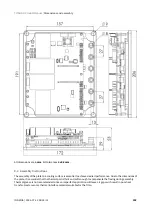
Страница 102: ...eight and 4 x Ø 9 mm holes for M8 screws mounting 8 1 Titan Go Dimensions Following are shown the Titan GO dimensions For further details download the 3D model Thermal dissipation required To reach its power specifications Titan Go must be mounted over a heatsink and a thermal interface material must be placed and compressed in between to ensure a good contact See below ...

Страница 103: ...a cooling surface is essential to achieve desired performance Due to the dimensions of the plate it is essential that the thermal pad is thick and soft enough to compensate the flexing during assembly Thermal grease is not recommended since an imperfect application will leave air gaps wich result in poor heat transfer Next are some thermal interface materials suitable for the Titan ...

Страница 104: ... with a big surface should be tacky and soft to prevent the formation of air bubbles Also thickness should be enough to compensate for the flexion of the plate while being compressed 0 5 mm is typically enough for this purpose Please note that thin high performance materials that look promising on the datasheet may end up with poor heat transfer With thin materials the pressure is only applied nea...

Страница 105: ...logy H48 6A 320 320 1 0 1A Adhesive one side 1 02 mm 4 0 W m K 0 006 K W 8 2 3 Screw assembly Screw the plate evenly Apply a torque that guarantees pressure on all the surface and does not bend the aluminum plate Recommended screw size is M8 Use stainless steel good quality screws The maximum screw torque is 9 Nm Higher torque will not result in better heat transfer as the plate would bend and pre...

Страница 106: ...TITAN GO Product Manual Dimensions and assembly INGENIA 2022 07 14 08 35 14 106 Description M8 stainless steel crinkle washer Image Part number Duratool D00829 Distributor codes Farnell 1614006 ...

Страница 107: ...r own application to communicate with the Titan Go and develop standalone or multiaxis systems you can use the multi platform library MCLIB 9 3 Arduino To start an Arduino based project easily connect using the serial RS485 port of the Titan Go and use our Arduino Library Ardulib Please make sure that your Arduino board has a RS232 port or that a suitable adaptor is used Keep the firmware updated ...

Страница 108: ... BARCELONA 10 Service We are committed to quality customer service In order to serve in the most effective way please open a ticket on our service desk at www ingeniamc com support or contact your local sales representative for assistance ...

Отзывы: