IDT Transparent Mode Operation
Generic PCI to PCI Bridge Register Definition
PES12N3 User Manual
9 - 42
June 7, 2006
Notes
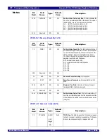
SWCTL - Switch Control (0x0A4)
23
INTD
RO
0x0
INTD Aggregated State. Aggregated switch state for
INTD.
0x0 - (negated) INTD negated
0x1 - (asserted) INTD asserted
24
LOCKDIS
RW1C
0x0
Lock Discard. When the upstream port is locked with a
downstream port and a TLP is received by the upstream
port that is destined to the unlocked downstream port, then
the TLP is dropped, this bit is set, and if error reporting is
enabled an ERR_NON_FATAL message is sent to the
root.
25
PMELOCK
RW1C
0x0
PME Lock Error. This bit is set when a PME_Turn_Off
message is received by a locked downstream PCI-PCI
bridge (i.e., that associated with port B or C). When this
occurs and error reporting is enabled, an
ERR_NON_FATAL message is sent to the root.
29:26
Reserved
RO
0x0
31:30
MAXLNKWDTH
RO
0x8
Maximum Link Width.
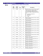
Bit
Field
Field
Name
Type
Default
Value
Description
0
RST
RW
0x0
Reset. Writing a one to this bit initiates a fundamental
reset. Writing a zero has no effect. This field always returns
a value of zero when read.
1
RSTHALT
RW
HWINIT
Reset Halt. When this bit is set, all of the switch logic
except the SMBus interface remains in a reset state. In this
state, registers in the device may be initialized by the slave
SMBus interface. When this bit is cleared, normal opera-
tion ensues.
Setting or clearing this bit has no effect following a reset
operation.
This bit may be set by asserting the RSTHALT signal dur-
ing a reset operation or through initialization by the serial
EEPROM.
2
REGUNLOCK
RW
0x0
Register Unlock. When this bit is set, the contents of reg-
isters and fields of type Read and Write when Unlocked
(RWL) are modified when written to. When this bit is
cleared, all registers and fields denoted as RWL become
read-only.
While the initial value of this field is cleared, it is set during
a reset operation, thus allowing serial EEPROM initializa-
tion to modify the contents of RWL fields.
3
DRO
RW
0x0
Disable Relaxed Ordering. The switch implements
relaxed ordering for TLPs with the relaxed ordering bit set.
When the DRO bit is set, the switch strongly orders all
transactions regardless of the state of the relaxed ordering
bit in TLPs.
Bit
Field
Field
Name
Type
Default
Value
Description
Содержание 89HPES12N3
Страница 10: ...IDT Table of Contents PES12N3 User Manual iv June 7 2006 Notes...
Страница 14: ...IDT List of Figures PES12N3 User Manual viii June 7 2006 Notes...
Страница 36: ...IDT Clocking Reset and Initialization Reset PES12N3 User Manual 2 8 June 7 2006 Notes...
Страница 40: ...IDT Link Operation Slot Power Limit Support PES12N3 User Manual 3 4 June 7 2006 Notes...
Страница 50: ...IDT Switch Operation Switch Core Errors PES12N3 User Manual 4 10 June 7 2006 Notes...
Страница 54: ...IDT Power Management Active State Power Management PES12N3 User Manual 5 4 June 7 2006 Notes...
Страница 62: ...IDT Hot Plug and Hot Swap Hot Swap PES12N3 User Manual 6 8 June 7 2006 Notes...
Страница 78: ...IDT SMBus Interfaces Slave SMBus Interface PES12N3 User Manual 7 16 June 7 2006 Notes...
Страница 142: ...IDT Transparent Mode Operation Generic PCI to PCI Bridge Register Definition PES12N3 User Manual 9 62 June 7 2006 Notes...
Страница 148: ...IDT Test and Debug SerDes Test Clock PES12N3 User Manual 10 6 June 7 2006...
Страница 158: ...IDT JTAG Boundary Scan Usage Considerations PES12N3 User Manual 11 10 June 7 2006 Notes...


