


IDT Transparent Mode Operation
Generic PCI to PCI Bridge Register Definition
PES12N3 User Manual
9 - 41
June 7, 2006
Notes
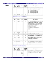
7
PALREV
RO
HWINIT
PCI Express Port A Lane Reverse. This bit reflects the
value of the PALREV signal sampled during the fundamen-
tal reset.
8
PBLREV
RO
HWINIT
PCI Express Port B Lane Reverse. This bit reflects the
value of the PBLREV signal sampled during the fundamen-
tal reset.
9
PCLREV
RO
HWINIT
PCI Express Port C Lane Reverse. This bit reflects the
value of the PCLREV signal sampled during the fundamen-
tal reset.
10
REFCLKM
RO
HWINIT
PCI Express Reference Clock Mode Select. This bit
reflects the value of the REFCLKM signal sampled during
the fundamental reset.
11
RSTHALT
RO
HWINIT
Reset Halt. This bit reflects the value of the RSTHALT sig-
nal sampled during the fundamental reset.
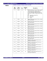
12
TSTRSVD
RO
HWINIT
Reserved. Reserved for future test mode. Must be tied to
ground.
16:13
MARKER
RW
0x0
Sticky
Marker. This field is preserved across a hot reset and is
available for general software use.
A hot reset does not result in modification of this field.
18:17
LOCKMODE
RO
0x0
Lock Mode. This field reflects the current locked status of
the switch.
0x0 - (unlocked) switch is unlocked
0x1 - (lockedab) port A is locked with downstream port B
0x2 - (lockedac) port A is locked with downstream port C
0x3 - reserved
19
LOCKDROP
RW1C
0x0
Locked Dropped. When the switch is locked and the
upstream port may become deadlocked due to a TLP being
received which cannot be forwarded due to the lock, then
the TLP is dropped and this bit is set.
This bit is also set and the transaction is dropped if the
switch is locked and a Memory Read Request - Locked
(MRdLK) transaction is received from a requester other
than the one which had locked the switch.
20
INTA
RO
0x0
INTA Aggregated State. Aggregated switch state for
INTA.
0x0 - (negated) INTA negated
0x1 - (asserted) INTA asserted
21
INTB
RO
0x0
INTB Aggregated State. Aggregated switch state for
INTB.
0x0 - (negated) INTB negated
0x1 - (asserted) INTB asserted
22
INTC
RO
0x0
INTC Aggregated State. Aggregated switch state for
INTC.
0x0 - (negated) INTC negated
0x1 - (asserted) INTC asserted
Bit
Field
Field
Name
Type
Default
Value
Description
Содержание 89HPES12N3
Страница 10: ...IDT Table of Contents PES12N3 User Manual iv June 7 2006 Notes...
Страница 14: ...IDT List of Figures PES12N3 User Manual viii June 7 2006 Notes...
Страница 36: ...IDT Clocking Reset and Initialization Reset PES12N3 User Manual 2 8 June 7 2006 Notes...
Страница 40: ...IDT Link Operation Slot Power Limit Support PES12N3 User Manual 3 4 June 7 2006 Notes...
Страница 50: ...IDT Switch Operation Switch Core Errors PES12N3 User Manual 4 10 June 7 2006 Notes...
Страница 54: ...IDT Power Management Active State Power Management PES12N3 User Manual 5 4 June 7 2006 Notes...
Страница 62: ...IDT Hot Plug and Hot Swap Hot Swap PES12N3 User Manual 6 8 June 7 2006 Notes...
Страница 78: ...IDT SMBus Interfaces Slave SMBus Interface PES12N3 User Manual 7 16 June 7 2006 Notes...
Страница 142: ...IDT Transparent Mode Operation Generic PCI to PCI Bridge Register Definition PES12N3 User Manual 9 62 June 7 2006 Notes...
Страница 148: ...IDT Test and Debug SerDes Test Clock PES12N3 User Manual 10 6 June 7 2006...
Страница 158: ...IDT JTAG Boundary Scan Usage Considerations PES12N3 User Manual 11 10 June 7 2006 Notes...


