IDT Transparent Mode Operation
Generic PCI to PCI Bridge Register Definition
PES12N3 User Manual
9 - 36
June 7, 2006
Notes
Power Management Capability Structure
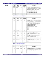
PMCAP - PCI Power Management Capabilities (0x070)
PMCSR - PCI Power Management Control and Status (0x074)
Bit
Field
Field
Name
Type
Default
Value
Description
7:0
CAPID
RO
0x1
Capability ID. The value of 0x1 identifies this capability as
a PCI power management capability structure.
15:8
NXTPTR
RO
0x7C for ports
B and C
0x0 for port A
Next Pointer. This field contains a pointer to the next
capability structure.
For port A the value of this field is 0x0 indicating that it is
the last capability.
For ports B and C, this field is 0x7C and points to the MSI
capability structure.
18:16
VER
RO
0x2
Power Management Capability Version. This field indi-
cates compliance with version two of the specification.
19
PMECLK
RO
0x0
PME Clock. Does not apply to PCI Express.
20
Reserved
RO
0x0
21
DEVSP
RWL
0x0
Device Specific Initialization. The value of zero indicates
that no device specific initialization is required.
24:22
AUXI
RO
0x0
AUX Current. not used
25
D1
RO
0x0
D1 Support. This field indicates that the PES12N3 does
not support D1.
26
D2
RO
0x0
D2 Support. This field indicates that the PES12N3 does
not support D2.
31:27
PME
RO
0b11001
PME Support. This field indicates the power states in
which the port may generate a PME.
Bits 27, 30 and 31 are set to indicate that the bridge will for-
ward PME messages.
The switch does not forward PME messages in D3
cold
.
This functionality may be supported in the system by rout-
ing WAKE# around the switch.
Bit
Field
Field
Name
Type
Default
Value
Description
1:0
PSTATE
RW
0x0
Power State. This field is used to determine the current
power state and to set a new power state.
0x0 - (d0) D0 state
0x1 - (d1) D1 state (not supported by PES12N3 and
reserved)
0x2-
(d2) D2 state (not supported by PES12N3 and
reserved)
0x3 - (d3) D3
hot
state
7:2
Reserved
RO
0x0
Содержание 89HPES12N3
Страница 10: ...IDT Table of Contents PES12N3 User Manual iv June 7 2006 Notes...
Страница 14: ...IDT List of Figures PES12N3 User Manual viii June 7 2006 Notes...
Страница 36: ...IDT Clocking Reset and Initialization Reset PES12N3 User Manual 2 8 June 7 2006 Notes...
Страница 40: ...IDT Link Operation Slot Power Limit Support PES12N3 User Manual 3 4 June 7 2006 Notes...
Страница 50: ...IDT Switch Operation Switch Core Errors PES12N3 User Manual 4 10 June 7 2006 Notes...
Страница 54: ...IDT Power Management Active State Power Management PES12N3 User Manual 5 4 June 7 2006 Notes...
Страница 62: ...IDT Hot Plug and Hot Swap Hot Swap PES12N3 User Manual 6 8 June 7 2006 Notes...
Страница 78: ...IDT SMBus Interfaces Slave SMBus Interface PES12N3 User Manual 7 16 June 7 2006 Notes...
Страница 142: ...IDT Transparent Mode Operation Generic PCI to PCI Bridge Register Definition PES12N3 User Manual 9 62 June 7 2006 Notes...
Страница 148: ...IDT Test and Debug SerDes Test Clock PES12N3 User Manual 10 6 June 7 2006...
Страница 158: ...IDT JTAG Boundary Scan Usage Considerations PES12N3 User Manual 11 10 June 7 2006 Notes...


