19: P
ULSE
O
UTPUT
I
NSTRUCTIONS
19-32
FT1A S
MART
A
XIS
U
SER
’
S
M
ANUAL
FT9Y-B1382
ARAMP (RAMP with Table)
When the initialization input specified by S2 is turned on, the initial values configured in the WindLDR ARAMP instruction are stored
in the control registers.
When the interrupt input configured by S3 is turned on, the step being executed is aborted and the interrupt step is executed.
The settings for the step being executed, including the preset value and the steady pulse frequency, are stored in the data
registers specified by D1.
The control status, including the pulse output status (output on, output direction, output complete), is set as the operation status
in the internal relays specified by D2.
Note:
Configure multiple PULS (pulse output), PWM (pulse width modulation), RAMP (ramp control), and ARAMP (RAMP with table) instructions so
that they do not share the same pulse output port.
However, the ZRN (zero return) instruction can be configured with the same pulse output port as the PULS (pulse output), PWM (pulse width
modulation), RAMP (ramp control), and ARAMP (RAMP with table) instructions.
Applicable CPU Modules
Note:
These instructions cannot be used with FT1A-H40RC and FT1A-B40RC.
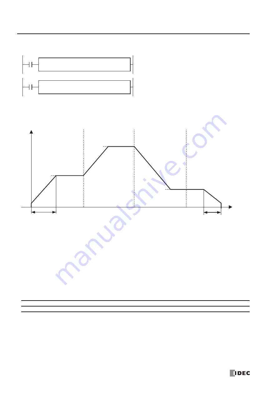
The ARAMP instructions output pulses with the frequency change
function according to the information in the frequency table.
When the input is on, pulses are output according to the frequency
change settings stored in the control register settings specified by S1.
The pulse frequency is controlled by combining multiple steps that define
the change time and steady pulse speed. The pulses change frequency
at a constant rate until they reach the steady pulse frequency in the step
option settings. You can select to output pulses at the steady pulse
frequency or to change the frequency at a constant rate until the steady
pulse frequency is reached after pulses that maintain the frequency in
the previous step are output. The next step is executed when the
number of pulses output reaches the preset value. You can configure a
maximum of 18 steps.
D2
*****
D1
*****
ARAMP
1
S3
*****
S2
*****
S1
*****
D2
*****
D1
*****
ARAMP
2
S3
*****
S2
*****
S1
*****
FT1A-12
FT1A-24
FT1A-40
FT1A-48
FT1A-Touch
—
—
X (Note)
X
—
Step 1
Step 2
Step 3
Step 4
Steady pulse
frequency
Frequency change time
Steady pulse
frequency
Steady pulse
frequency
Before
Frequency change time
Frequency
Before
Before
After
Time
Содержание microsmart pentra
Страница 1: ...FT1A SERIES FC9Y B1382 Ladder Programming Manual ...
Страница 6: ...Preface 5 FT1A SMARTAXIS USER S MANUAL FT9Y B1382 ...
Страница 104: ...7 DATA COMPARISON INSTRUCTIONS 7 10 FT1A SMARTAXIS USER S MANUAL FT9Y B1382 ...
Страница 122: ...8 BINARY ARITHMETIC INSTRUCTIONS 8 18 FT1A SMARTAXIS USER S MANUAL FT9Y B1382 ...
Страница 138: ...10 SHIFT ROTATE INSTRUCTIONS 10 12 FT1A SMARTAXIS USER S MANUAL FT9Y B1382 ...
Страница 162: ...11 DATA CONVERSION INSTRUCTIONS 11 24 FT1A SMARTAXIS USER S MANUAL FT9Y B1382 ...
Страница 188: ...12 CALENDAR COMPARISON INSTRUCTIONS 12 26 FT1A SMARTAXIS USER S MANUAL FT9Y B1382 ...
Страница 198: ...15 REFRESH INSTRUCTIONS 15 4 FT1A SMARTAXIS USER S MANUAL FT9Y B1382 ...
Страница 202: ...16 INTERRUPT CONTROL INSTRUCTIONS 16 4 FT1A SMARTAXIS USER S MANUAL FT9Y B1382 ...
Страница 266: ...20 DUAL TEACHING TIMER INSTRUCTIONS 20 4 FC5A MICROSMART USER S MANUAL FC9Y B1273 ...
Страница 318: ...25 USER COMMUNICATION INSTRUCTIONS 25 22 FT1A SMARTAXIS USER S MANUAL FT9Y B1382 ...


