


p. 23 / 39
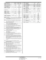
M18 – HARMONIC PROTECTION
(HARn, n=1…4)
UoM
Default
Range
P18.n.01
CT primary
A
5
1 - 30000
P18.n.02
CT secondary
A
5
1-5
P18.n.03
CT wiring
2 Aron
2 Aron
1 bilanciato
P18.n.04
Nominal current
A
5
1 - 30000
P18.n.05
CT positioning
Global
Global
Step 1
Step 2
….
Step 8
P18.n.06
Current limit
%
OFF
OFF / 100 - 200
P18.n.07
Current THD Limit
%
OFF
OFF / 1 – 100
P18.n.08
5rd Harmonic limit
%
OFF
OFF / 1 – 100
P18.n.09
7th Harmonic limit
%
OFF
OFF / 1 – 100
P18.n.10
11th Harmonic limit
%
OFF
OFF / 1 – 100
P18.n.11
13th Harmonic limit
%
OFF
OFF / 1 – 100
P18.n.12
Temperature alarm
threshold 1
°
55
0-212
P18.n.13
Temperature alarm
threshold 2
°
55
0-212
Note: Parameters in this menu are referred to protections that are available only when
using the harmonic protection module EXP1016.
P18.n.01 - P18.n.02
- Primary and secondary of the CT used for current measurement in
power factor correction panel and connected to the harmonics protection module.
P18.n.03
- Current measurement wiring mode:
2 in Aron - Reading of three currents (three-phase) with two CT in Aron configuration.
1 balanced - Reading a single current from a single CT.
P18.n.04
- Rated current flowing in the power factor correction branch under normal conditions.
P18.n.05
- branch of the circuit where are located the CT for harmonic protection measure.
P18.n.06
- Max current threshold in the power factor correction branch, used for generation of
alarm A11.
P18.n.07
- Current THD maximum threshold in the branch of power factor correction. Used for
generation of alarm A12.
P18.n.08
- Threshold 5th harmonic content in the branch of power factor correction. Used for
generation of alarm A13.
P18.n.09
- Threshold 7th harmonic content in the branch of power factor correction. Used for
generation of alarm A14.
P18.n.10
- Threshold 11th harmonic content in the branch of power factor correction. Used for
generation of alarm A15.
P18.n.11
- Threshold 13th
harmonic content in the branch of power factor correction. Used for
generation of alarm A16.
P18.n.12 - P18.n.13
- Maximum temperature thresholds 1 and 2 on the sensors connected to
the harmonics protection module. Used to generate alerms A17 and A18.
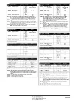
M18 – HARMONIC PROTECTION
(HARn, n=1…4)
Ед.
изм.
По ум.
Диапазон
P18.n.01
ТТ первичная
A
5
1 - 30000
P18.n.02
ТТ вторичная
A
5
1-5
P18.n.03
Подключение ТТ
2 Арон
2 Арон
1 сбалансированное
P18.n.04
Номинальный ток
A
5
1 - 30000
P18.n.05
Положение ТТ
Глобально
Глобально
Ступень 1
Ступень 2
….
Ступень 8
P18.n.06
Предел тока
%
ВЫКЛ.
ВЫКЛ. / 100 – 200
P18.n.07
Предел КНИ тока
%
ВЫКЛ.
ВЫКЛ. / 1 – 100
P18.n.08
Предел 5-ой гармоники
%
ВЫКЛ.
ВЫКЛ. / 1 – 100
P18.n.09
Предел 7-ой гармоники
%
ВЫКЛ.
ВЫКЛ. / 1 – 100
P18.n.10
Предел 11-ой гармоники
%
ВЫКЛ.
ВЫКЛ. / 1 – 100
P18.n.11
Предел 13-ой гармоники
%
ВЫКЛ.
ВЫКЛ. / 1 – 100
P18.n.12
Порог аварийного сигнала
температуры 1
°
55
0-212
P18.n.13
Порог аварийного сигнала
температуры 2
°
55
0-212
Примечание.
Параметры в этом меню относятся к защитам, которые доступны
только при использовании модуля защиты от гармоник EXP1016.
P18.n.01 - P18.n.02
– Первичная и вторичная обмотка ТТ для измерения тока на панели
корректировки коэффициента мощности и подключенная к модулю защиты от
гармоник.
P18.n.03
– Режим подключения измерения тока:
2 в Арон – считывание трех значений тока (три фазы) с двумя ТТ в
конфигурации Арон.
1 сбалансированный – считывание одного значения тока отдельного ТТ.
P18.n.04
– Номинальный ток, перетекающий в ветвь корректировки коэффициента
мощности в нормальных условиях.
P18.n.05
– Ветвь цепи, где расположены ТТ для измерения защиты от гармоник.
P18.n.06
– Порог максимального тока в ветви корректировки коэффициента мощности,
по которому создается аварийный сигнал A11.
P18.n.07
- Порог максимального КНИ тока в ветви коррекции коэффициента мощности.
Используется для создания аварийного сигнала A12.
P18.n.08
– Порог 5-го коэффициента гармоник в ветви корректировки коэффициента
мощности. Используется для создания аварийного сигнала A13.
P18.n.09
– Порог 7-го коэффициента гармоник в ветви корректировки коэффициента
мощности. Используется для создания аварийного сигнала A14.
P18.n.10
– Порог 11-го коэффициента гармоник в ветви корректировки коэффициента
мощности. Используется для создания аварийного сигнала A15.
P18.n.11
– Порог 13-го
коэффициента гармоник в ветви корректировки коэффициента
мощности. Используется для создания аварийного сигнала A16.
P18.n.12 - P18.n.13
– Пороги максимальной температуры 1 и 2 на датчиках,
подключенных к модулю защиты от гармоник. Используются для создания
аварийных сигналов A17 и A18.
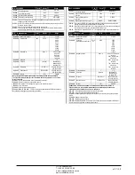
M19 - MISCELLANEOUS
UoM
Default
Range
P19.01
Step disconnection passing
in MAN mode
OFF
OFF/ON
P19.01 -
If set to ON, when switching from AUT mode to MAN mode, steps are disconnected in
sequence.
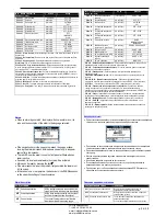
M19 - MISCELLANEOUS
Ед.
изм.
По ум.
Диапазон
P19.01
Отключение ступени при
переходе в режим MAN
ВЫКЛ.
ВЫКЛ./ВКЛ.
P19.01 –
Если задано ВКЛ., то при переходе из режима AUT (АВТОМАТИЧЕСКИЙ) в
режим MAN (РУЧНОЙ) ступени подключаются последовательно.
M20 – LIMIT THRESHOLDS
(LIMn, n=1…16)
UoM
Default
Range
P20.n.01
Reference measurement
OFF
OFF- (misure)
P20.n.02
Channel nr. (x)
1
OFF / 1-99
P20.n.03
Function
Max
Max – Min – Min+Max
P20.n.04
Upper threshold
0
-9999 - +9999
P20.n.05
Multiplier
x1
/100 – x10k
P20.n.06
Delay
s
0
0.0 – 600.0
P20.n.07
Lower threshold
0
-9999 - +9999
P20.n.08
Multiplier
x1
/100 – x10k
P20.n.09
Delay
s
0
0.0 – 600.0
P20.n.10
Idle state
OFF
OFF-ON
P20.n.11
Memeory
OFF
OFF-ON
Note: this menu is divided into 16 sections for the limit thresholds LIM1..16
P20.n.01
– Defines to which DCRG8 measurements the limit threshold applies.
P20.n.02
– If the reference measurement is an internal multichannel measurement (AINx for
example), the channel is defined.
P20.n.03
–
Defines the operating mode of the limit threshold.
Max
= LIMn enabled when the
measurement exceeds P20.n.04. P20.n.07 is the reset threshold.
Min
= LIMn enabled
when the measurement is less than P20.n.07. P20.n.04 is the reset threshold.
Min+Max
= LIMn enabled when the measurement is greater than P20.n.04 or less
than P20.n.07.
P20.n.04
and
P20.n.05 -
Define the upper threshold, obtained by multiplying value P20.n.04 by
P20.n.05.
P20.n.06
- Upper threshold intervention delay.
P20.n.07, P08.n.08, P08.n.09
- As above, with reference to the lower threshold.
P20.n.10
- Inverts the state of limit LIMn.
P20.n.11
- Defines whether the threshold remains memorized and is reset manually through
command menu (ON) or if it is reset automatically (OFF).
M20 – LIMIT THRESHOLDS
(LIMn, n=1…16)
Ед.
изм.
По ум.
Диапазон
P20.n.01
Контрольное измерение
ВЫКЛ.
ВЫКЛ. (измерение)
P20.n.02
№ канала (x)
1
ВЫКЛ. / 1-99
P20.n.03
Функция
Макс.
Макс. – Мин. –
Мин.+Макс.
P20.n.04
Верхний порог
0
-9999 - +9999
P20.n.05
Множитель
x1
/100 – x10k
P20.n.06
Задержка
с
0
0,0 – 600,0
P20.n.07
Нижний порог
0
-9999 - +9999
P20.n.08
Множитель
x1
/100 – x10k
P20.n.09
Задержка
с
0
0,0 – 600,0
P20.n.10
Состояние простоя
ВЫКЛ.
ВЫКЛ.-ВКЛ.
P20.n.11
Память
ВЫКЛ.
ВЫКЛ.-ВКЛ.
Примечание. Это меню состоит из 16 частей для пороговых пределов LIM1..16.
P20.n.01
– Определяет, к каким измерениям DCRG8 применяется пороговый предел.
P20.n.02
– Если контрольное измерение является внутренним многоканальным
измерением (например, AINx), то определяет канал.
P20.n.03
–
Определяет режим работы порогового предела.
Макс.
= LIMn включается при
превышении значения измерения P20.n.04. P20.n.07 является порогом для
сброса.
Мин.
= LIMn включается при недостижении значением измерения
P20.n.07. P20.n.04 является порогом для сброса.
Мин.+Макс.
= LIMn
включается, если значение измерения больше P20.n.04 или меньше P20.n.07.
P20.n.04
и
P20.n.05 –
Определяют верхний порог, получаемый путем умножения
значения P20.n.04 на P20.n.05.
P20.n.06
– Рабочая задержка верхнего порога.
P20.n.07, P08.n.08, P08.n.09
– Как выше, но с учетом нижнего порога.
P20.n.10
– Инвертирует состояние предела LIMn.
P20.n.11
–Определяет, запоминается ли порог и сбрасывается ли он вручную в меню
команд (ВКЛ.) или автоматически (ВЫКЛ.).
ЧП
«
Профиэлектро
»
Т
. +380 44 361-62-55, 80
e-mail: [email protected]
www. profielectro.net.ua


