


p. 19 / 39
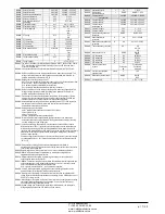
M03 – STEP
(STPn, n=1…32)
UoM
Default
Range
P03.n.01
Step weight
OFF
OFF/ 1 – 99
P03.n.02
Step insertion type
Contactor
Contactor
Static
Note: This menu is divided into 32 sections that refer to 32 possible logical steps
STP1…STP32 which can be managed by the DCRG.
P03.n.01
- Weight of step n, referred to the value of the smallest step. A number that indicates
the multiple of the power of the current step with reference to the smallest set by
P02.07. If set to OFF the step is disabled and will not be used.
P03.n.02
- Type device delegated the insertion step.
Contactor = Switching with electromechanical contactor. On this step the time of
reconnection is used.
Static = Electronic thyristor switching. On this step the time of reconnection is not
considered . Used for Fast power factor correction.
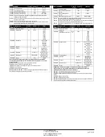
M03 – STEP
(STPn, n=1…32)
Ед.
изм.
По ум.
Диапазон
P03.n.01
Вес ступени
ВЫКЛ.
ВЫКЛ. / 1 – 99
P03.n.02
Тип подключения
ступени
Контактор
Контактор
Статический
Примечание.
Это меню состоит из 32 частей, относящихся к 32 возможным
логическим ступеням STP1…STP32, управление которыми может
осуществлять DCRG.
P03.n.01
– Вес ступени n, связан со значением самой малой ступени. Номер,
обозначающий множитель мощности текущей ступени на основе наименьшего
значения, заданного в параметре P02.07. Если выбрано ВЫКЛ., то ступень
отключается и не используется.
P03.n.02
– Т – тип устройства, которому поручено подключение ступени.
Контактор = переключение с помощью электромеханического контактора. В этой
ступени используется время переподключения ступени.
Статический = переключение электронным тиристором. В этой ступени время
переподключения не учитывается. Используется для быстрой корректировки
коэффициента мощности.
M04 –MASTER OUTPUTS
(OUTn, n=1…16)
UoM
Default
Range
P04.n.01
Output OUTn function
n=1…8
Step x
See
n=9…16
OFF
Output function table
P04.n.02
Channel number x
n=1…8
x=1…8
1 – 99
n=9…16
x=1
P04.n.03
Output normal/reversed
NOR
NOR
REV
Note: This menu is divided into 16 sections that refer to 16 possible digital outputs
OUT1…OUT16, which can be managed by the master DCRG8; OUT81..OUT08
on the base board and OUT09…OUT16 on any installed expansion modules.
P04.n.1
– Selects the functions of the selected output (see programmable outputs functions
table).
P04.n.2
– Index associated with the function programmed in the previous parameter. Example:
If the output function is set to
Alarm Axx
, and you want this output to be energized for
alarm A31, then P04.n.02 should be set to value 31.
P04.n.3
- Sets the state of the output when the function associated with the same is inactive:
NOR
= output de-energized,
REV
= output energized.
M04 –MASTER OUTPUTS
(OUTn, n=1…16)
Ед.
изм.
По ум.
Диапазон
P04.n.01
Функция выходного
сигнала OUTn
n=1…8
Ступень x
См.
n=9…16
ВЫКЛ.
Таблица функций
выходов
P04.n.02
Номер канала x
n=1…8
x=1…8
1 – 99
n=9…16
x=1
P04.n.03
Нормальный/обратный
выход
NOR
NOR
REV
Примечание.
Это меню состоит из 16 частей, относящихся к 16 возможным
цифровым выходам OUT1…OUT16, управление которыми может
осуществлять ведущее устройство DCRG; выходы OUT01..OUT08 на
главной плате и выходы OUT09…OUT16 на любых установленных
модулях расширения.
P04.n.1
– Выбор функций выбранного выхода (см. таблицу функций программируемых
выходов).
P04.n.2
– Порядковый номер, связанный с функцией, запрограммированной с помощью
предыдущего параметра. Пример. Если функция выхода задана как
Alarm Axx
(Аварийный сигнал Axx)
и на этот выход требуется подавать напряжение в
случае аварийного сигнала A31, то параметру P04.n.02 следует присвоить
значение 31.
P04.n.3
– Определяет состояние выхода при неактивной связанной функции:
NOR
= нет
напряжения на выходе,
REV
= напряжение на выходе.
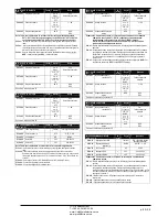
M05 – MASTER / SLAVE
UoM
Default
Range
P05.01
Master-Slave function
OFF
OFF
COM1
COM2
P05.02
Device role
Master
Master
Slave01
Slave02
Slave03
…
Slave08
P05.03
Slave 1 enable
OFF
OFF-ON
P05.04
Slave 2 enable
OFF
OFF-ON
P05.05
Slave 3 enable
OFF
OFF-ON
P05.06
Slave 4 enable
OFF
OFF-ON
P05.07
Slave 5 enable
OFF
OFF-ON
P05.08
Slave 6 enable
OFF
OFF-ON
P05.09
Slave 7 enable
OFF
OFF-ON
P05.10
Slave 8 enable
OFF
OFF-ON
P05.01
- Defines whether the system is used in master-slave configuration or not. OFF the
system works with a single controller (normal configuration). If you set COM1 or
COM2, working in master mode and slave setting indicates which communication
channel is used for communication between controllers.
P05.02
- Defines whether the current device is a master or a slave, and in this case, which is
his number.
P05.03… P05.10
- Enables the operation of individual slaves.
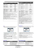
M05 – MASTER / SLAVE
Ед.
изм.
По ум.
Диапазон
P05.01
Функция «ведущее-
подчиненное устройство»
ВЫКЛ.
ВЫКЛ.
COM1
COM2
P05.02
Роль устройства
Master
Master
Slave01
Slave02
Slave03
…
Slave08
P05.03
Подчиненное устройство 1
вкл.
ВЫКЛ.
ВЫКЛ.-ВКЛ.
P05.04
Подчиненное устройство 2
вкл.
ВЫКЛ.
ВЫКЛ.-ВКЛ.
P05.05
Подчиненное устройство 3
вкл.
ВЫКЛ.
ВЫКЛ.-ВКЛ.
P05.06
Подчиненное устройство 4
вкл.
ВЫКЛ.
ВЫКЛ.-ВКЛ.
P05.07
Подчиненное устройство 5
вкл.
ВЫКЛ.
ВЫКЛ.-ВКЛ.
P05.08
Подчиненное устройство 6
вкл.
ВЫКЛ.
ВЫКЛ.-ВКЛ.
P05.09
Подчиненное устройство 7
вкл.
ВЫКЛ.
ВЫКЛ.-ВКЛ.
P05.10
Подчиненное устройство 8
вкл.
ВЫКЛ.
ВЫКЛ.-ВКЛ.
P05.01
– Определяет, работает ли система в конфигурации «ведущее-подчиненное
устройство» или нет. ВЫКЛ. система работает с одним регулятором (обычная
конфигурация). Если задано COM1 или COM2, то при работе в режиме
ведущего устройства с заданным подчиненным устройством, эта настройка
определяет, какой канал связи используется для связи регуляторов.
P05.02
– Определяет, является ли текущее устройство ведущим или подчиненным, и в
этом случае – его номер.
P05.03… P05.10
– Включает отдельные подчиненные устройства.
ЧП
«
Профиэлектро
»
Т
. +380 44 361-62-55, 80
e-mail: [email protected]
www. profielectro.net.ua


