background image


                                                                                                                                                                           p. 10 / 39


named LIMx will be activated when the measurements will go outside the 
limits defined by the user through the dedicated setting menu. 


Furthermore, there are up to 8 counters (CNT1..CNT8) that can count 
pulses coming from an external source (through a digital input INPx) or the 
number of times that a certain condition as been verified. For instance, 
defining a limit threshold LIMx as the count source, it will be possible to 
count how many times one measurement has exceeded a certain limit. 


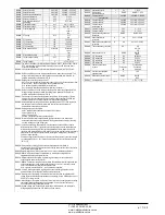
The following table groups all the I/O and the internal variables managed 
by the DCRG8. 


CODE 

DESCRIPTION 

 RANGE 

LIMx 

Limit thresholds 

1…16 

REMx 

Remote-controlled variables 

1…16 

UAx 

User alarms 

1…8 

PULx 

Energy consumption pulses 

1…3 

CNTx 

Programmable counters 

1…8 


пределы, определенные пользователем в специальном меню настройки, 

будет активироваться внутренняя переменная LIMx. 


Более того, имеется до 8 счетчиков (CNT1..CNT8), которые могут считать 

импульсы, поступающие с внешнего источника (по цифровому входу INPx), 
или число раз возникновения какого-либо условия. Например, определив 

пороговый предел LIMx как источник отсчета, можно будет отсчитать 
количество раз превышения определенного предела отдельным 

измерением. 


В следующей таблице сгруппированы все входы-выходы и внутренние 

переменные, доступные в DCRG8. 


КОД


ОПИСАНИЕ


ДИАПАЗОН


LIMx


Пороговые пределы 

1…16 

REMx


Дистанционно управляемые переменные 

1…16 

UAx


Пользовательские аварийные сигналы 

1…8 

PULx


Импульсы потребления энергии 

1…3 

CNTx


Программируемые счетчики 

1…8 


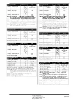
Limit thresholds (LIMx) 


The LIMn thresholds are internal variables whose status depends on the 
out-of-limits of one particular measurement set by the user (e.g. total active 
power higher than 25kW) among all those measured. 


To make the setting of the thresholds easier, since the limits can span in a 
very wide range, each of them can be set using a base number and a 
multiplier (for example: 25 x 1k = 25000). 


For each LIM, there are two thresholds (upper and lower). The upper 
threshold must always be set to a value higher than the lower threshold. 


The meaning of the thresholds depends on the following functions: 


Min function: 

the lower threshold defines the trip point, while the upper 

threshold is for the resetting. The LIM trips when the selected measurement is 
less than the Lower threshold for the programmed delay. When the measured 
value becomes higher than the upper setpoint, after the set delay, the LIM 
status is reset. 

Max function: 

the


upper threshold defines the trip point, while the lower 

threshold is for the resetting. The LIM trips when the selected measurement is 
more than upper threshold for the programmed delay. When the measured 
value decreases below the lower setpoint, after the delay,  the LIM  status is 
reset.  

Max+Min function:  

both thresholds are for tripping. When the measured 

value is less than lower or more than upper setpoints, then, after the 
respective delays, the LIM will trip. When the measured value returns within 
the limits, the LIM status will be immediately reset. 


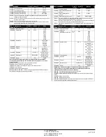
 Trip denotes either activation or de-activation of the LIM variable, 
depending on ‘Normal status’ setting. 


If the LIMn latch is enabled, the reset can be done only manually using the 
dedicated command in the commands menu. 


See setup menu M24. 


Пороговые пределы (LIMx)


Пороговые пределы LIMn представляют собой внутренние переменные, 

состояние которых зависит от выхода какого-либо измеренного и заданного 
пользователем значения за пределы установленных диапазонов 

(например, превышение общей активной мощности порога в 25 кВт). 


Для упрощения настройки порога (поскольку предельные значения могут 

варьироваться в очень широком диапазоне) каждый из них задается с 
использованием числа и множителя (пример: 25 x 1k = 25000). 


Для каждого значения LIM существуют два порога (верхний и нижний). 

Значение верхнего порога всегда должно быть больше значения нижнего 
порога. 


Значение порогов зависит от следующих функций: 


Функция Min (Минимум): 

нижний порог определяет точку срабатывания, а 

верхний порог служит для сброса. Порог LIM срабатывает, когда выбранное 

измерение меньше нижнего порога при запрограммированной задержке. Как 
только измеренное значение становится больше верхней уставки после 

заданной задержки, состояние LIM сбрасывается. 

Функция Max (Максимум): 

верхний порог определяет точку срабатывания, а 

нижний порог служит для сброса. Порог LIM срабатывает, когда выбранное 
измерение больше верхнего порога при запрограммированной задержке. Как 

только измеренное значение становится меньше нижней уставки после 
заданной задержки, состояние LIM сбрасывается.  

Функция Max+Min (Максимум+минимум): 

срабатывание происходит на 

обоих порогах. Как только измеренное значение становится меньше или 

больше верхней уставки, LIM срабатывает после установленных задержек. 
После возврата измеренного значения в предельный диапазон состояние LIM 

сбрасывается незамедлительно. 


 Срабатывание означает активацию или деактивацию переменной LIM, в 

зависимости от настройки параметра «Normal status» (Нормальное 
состояние). 


При активации фиксации LIMn, сброс можно выполнить только вручную с 
помощью специальной команды в меню команд. 


См. меню настройки M24.


Remote-controlled variables (REMx) 


DCRG8 can manage up to 16 remote-controlled variables 
(REM1…REM16). 


Those are variables which status can be modified by the user through the 
communication protocol and that can be used in combination with outputs.  


Example: using a remote variable (REMx) as a source for an output 
(OUTx), it will be possible to freely energise or de-energise one relay 
through the supervision software. This allows to use the DCRG8 relays to 
drive lighting or similar loads. 


Дистанционно управляемые переменные (REMx) 


Устройство DCRG8 поддерживает до 16 дистанционно управляемых 
переменных (REM1…REM16). 


Это переменные, состояние которых пользователь может изменить через 

протокол связи и которые можно использовать в сочетании с выходами.  


Пример: использование удаленной переменной (REMx) в качестве 

источника для выхода (OUTx) позволит свободно подать или снять 
напряжение с одного реле посредством управляющего ПО. Таким образом, 

реле DCRG8 могут управлять освещением или аналогичными нагрузками.  


Тип измерения 

Функция 

Значение измерения 

Верхний порог 

Задержка порога 

Нижний порог 


Состояние переменной 

предела 

Type of


measure 

Function 

Tipo di misura 

Upper threshold 

Threshold delay 

Lower threshold 


Status of the limit 

variable 

ЧП

 «

Профиэлектро

» 

Т

. +380 44 361-62-55, 80 

e-mail: [email protected] 

www. profielectro.net.ua 

Содержание RPC 8BGA

Страница 1: ...Main menu 4 Password access 4 Display page navigation 5 Table of display pages 5 Harmonic analysis page 7 Waveform pages 7 Expandability 8 Additional resources 9 Communication channels 9 Inputs output...

Страница 2: ...y outputs o Additional analog I O for PT100 temperature current voltage Capability to operate with several units interconnected in Master Slave mode o Maximum configuration Master 8 slave o Max 32 ste...

Страница 3: ...t the step is not available because its reconnection time is not yet exhausted In this case sending a command to close the step number will flash to indicate that the operation has been confirmed and...

Страница 4: ...d and the access is free If instead the passwords have been enabled and defined then to get access it is necessary to enter the password first specifying the numeric code through the keypad To enable...

Страница 5: ...o the display remains were it was last You can set this function in menu M01 Utility M01 Utility Table of display pages PAGES EXAMPLE Home page Power Voltage and current Step life statistics Temperatu...

Страница 6: ...function is disabled For example if the limit function is not programmed the corresponding page won t be shown Event time stamp Event description Event number total Key switches between Total Partial...

Страница 7: ...eric format selecting the required order through and The lower part of the screen will display a little arrow that points to the selected column and the relative percentage value of the three phases T...

Страница 8: ...figuration will be saved and will become effective otherwise the mismatch will be shown at every subsequent power on of the system The present system configuration is shown in the dedicated page of th...

Страница 9: ...hernet RS485 DCRG RS 485 Ethernet DCRG Ethernet COM1 COM2 COM3 Gateway DCRG Gateway Inputs outputs internal variables counters analog inputs The inputs and outputs are identified by a code and a seque...

Страница 10: ...is less than the Lower threshold for the programmed delay When the measured value becomes higher than the upper setpoint after the set delay the LIM status is reset Max function the upper threshold de...

Страница 11: ...protections like panel or capacitor overtemperature no voltage release harmonic protections etc The maximum possible configuration is one master with 8 slaves Example 1 application in series It is req...

Страница 12: ...gical step and pairing step between logical and physical outputs of the master and the slave The program is then automatically extended to the slaves On the slave it is only necessary to set the slave...

Страница 13: ...8 guaranteeing the greatest safety for the operator o High speed data transfer o IP54 front panel o Limits the possibility of unauthorized access with device config Simply hold the CX dongle up to the...

Страница 14: ...e panel M18 HARMONIC PROT Harmonic protections EXP1016 module M19 MISCELLANEOUS Various settings M20 LIMIT THRESHOLDS Limit thresholds on measurements M21 COUNTERS Generic programmable counters M22 AN...

Страница 15: ...to go back to the parameter selection The entered value is stored Press to save all the settings and to quit the setup menu The controller executes a reset and returns to normal operation If the user...

Страница 16: ...estore delay when no key pressed If set to OFF the display will always show the last page selected manually P01 08 Default page displayed on power up and after delay P01 09 Free text with alphanumeric...

Страница 17: ...number of the step on the main page is shown in light gray P02 11 Connection sensitivity This parameter sets the speed of reaction of the controller With small values of P02 11 regulation is fast more...

Страница 18: ...ws to avoid regulation oscillations Set this value according to the technical characteristics closing time declared by the manufacturer of the static contactor P02 30 Enables the setting of the setpoi...

Страница 19: ...the previous parameter Example If the output function is set to Alarm Axx and you want this output to be energized for alarm A31 then P04 n 02 should be set to value 31 P04 n 3 Sets the state of the...

Страница 20: ...4 PROGRAMMABLE INPUTS INPn n 1 8 UdM Default Range P14 n 01 INPn input function various see Input functions table P14 n 02 Function index x OFF OFF 1 99 P14 n 03 Contact type NO NO NC P14 n 04 Delay O...

Страница 21: ...U Modbus ASCII Modbus TCP P16 n 06 IP address 192 168 1 1 000 000 000 000 255 255 255 255 P16 n 07 Subnet mask 255 255 255 0 000 000 000 000 255 255 255 255 P16 n 08 IP port 1001 0 9999 Note this menu...

Страница 22: ...milar P17 08 Trip threshold for the capacitors overload protection alarm A08 that will arise after a integral delay time inversely proportional to the value of the overload P17 09 Threshold beyond whi...

Страница 23: ...100 P18 n 08 5 1 100 P18 n 09 7 1 100 P18 n 10 11 1 100 P18 n 11 13 1 100 P18 n 12 1 55 0 212 P18 n 13 2 55 0 212 EXP1016 P18 n 01 P18 n 02 P18 n 03 2 1 P18 n 04 P18 n 05 P18 n 06 A11 P18 n 07 A12 P18...

Страница 24: ...ould be connected to the appropriate terminal for the type selected See input module manual P22 n 02 and P22 n 03 Define the value to display for a min sensor signal in other words at the start of the...

Страница 25: ...Active energy Kvarh Reactive energy kVA Apparent energy P24 n 02 The quantity of energy which must accumulate for a pulse to be emitted for example 10Wh 100Wh 1kWh etc P24 n 03 Pulse duration Applicat...

Страница 26: ...function P26 n 10 Modem call A modem is connected as configured in setup P26 n 11 No LCD The alarm is managed normally but not shown on the display P26 n 12 13 Delay time Time delay in minutes or sec...

Страница 27: ...eshold set with P18 n 11 A17 Harmonic protection Module nr n Temperature 1 too high The temperature 1 measured by the harmonic protection module is higher than threshold set with P18 n 12 A18 Harmonic...

Страница 28: ...LOC 10 A19 LEN GEN 0 UAx GEN 0 Input function table The following table shows all the functions that can be attributed to the INPn programmable digital inputs Each input can be set for an reverse fun...

Страница 29: ...Energised when global alarm 2 is active Global alarm 3 Energised when global alarm 3 is active Fan Panel ventilation fan Manual mode Active when the regulator is in MAN mode Automatic mode Active when...

Страница 30: ...Senphi L3 26 W TOT Total active power 27 var TOT Total reactive power 28 VA TOT Total apparent power 29 Cosphi TOT Cosphi balanced three phase system 30 Senphi TOT Senphi balanced three phase system...

Страница 31: ...he backup of user settings Once the required command has been selected press to execute it The device will prompt for a confirmation Pressing again the command will be executed To cancel the command e...

Страница 32: ...arameter setting P02 03 Three phase P02 04 L3 P02 06 L1 L2 P02 22 LV P02 03 P02 04 L3 P02 06 L1 L2 P02 22 Single phase wiring SINGLE PHASE CONNECTION Voltage measure 1 phase voltage reading L1 N 1 L1...

Страница 33: ...2 22 FULL THREE PHASE CONNECTION WITH NEUTRAL Wiring configuration used for standard applications with full three phase voltage control Voltage measure 3 ph to n and 3 ph to ph voltage readings L1 N L...

Страница 34: ...V P02 23 ON P02 03 P02 04 L3 P02 06 L1 L2 P02 22 P02 23 Configuration with MV measurement and correction Voltage measure 3 ph to ph voltage reading L1 L2 L2 L3 L3 L1 on MV side 3 L1 L2 L2 L3 L3 L1 Cur...

Страница 35: ...0 90 Capacitor overload current measure 3 Readings on L1 L2 L2 L3 L3 L1 3 L1 L2 L2 L3 L3 L1 Parameter setting P02 03 Three phase P02 04 L1 L2 L3 P02 06 L1 L2 L3 P02 22 LV P02 29 Fast P02 03 P02 04 L1...

Страница 36: ...01 Stepx P07 1 01 Stepx P08 1 02 Stepx P05 01 COM1 P05 02 Slave01 P05 01 COM1 P05 02 Slave02 P05 01 COM1 P05 02 Slave03 P05 01 COM1 P05 02 P05 03 P05 04 P05 05 P04 1 01 x P06 1 01 x P07 1 01 x P08 1 0...

Страница 37: ...morsetti OUT 1 600V 50 60 Hz OUT 2 OUT 3 OUT 4 OUT 5 OUT 6 OUT 7 OUT 8 SLOT 1 SLOT 2 SLOT 3 SLOT 4 Dimensioni meccaniche e foratura pannello mm 380 44 361 62 55 80 e mail info profielectro net ua www...

Страница 38: ...age 415V 415 Rated current AC1 5A 250V AC15 1 5A 415V AC1 5A 250 AC15 1 5A 415 Real time clock Energy storage Back up capacitors Operating time without supply voltage About 12 15 days 12 15 Insulation...

Страница 39: ...phase neutral voltage 300V 300 Rev Date Notes 00 30 10 2012 First release 00 30 10 2012 01 28 01 2013 Added Tanfi parameters P02 30 e P02 31 01 28 01 2013 tanfi P02 30 P02 31 380 44 361 62 55 80 e ma...

Отзывы: