


p. 8 / 39
Expandability
Thanks to expansion bus, the DCRG8 can be expanded with EXP…
series modules.
It is possible to connect a maximum of 4 EXP… modules at the same
time.
The supported EXP modules can be grouped in the following categories:
o
additional steps
o
communication modules
o
digital I/O modules
o
Analog I/O modules.
To insert an expansion module:
o
remove the power supply to DCRG8
o
remove the protecting cover of one of the expansion slots
o
insert the upper hook of the module into the fixing hole on the top of
the expansion slot
o
rotate down the module body, inserting the connector on the bus
o
push until the bottom clip snaps into its housing.
Расширяемость
Благодаря шине расширения, устройство DCRG8 можно дополнительно
оснастить модулями серии EXP.
Одновременно можно подключить не более 4-х модулей EXP.
Поддерживаемые модули EXP можно объединить в следующие
категории:
o
дополнительные ступени
o
модули связи
o
модули цифровых входов-выходов
o
модули аналоговых входов-выходов.
Порядок вставки модуля расширения:
o
отключите питание DCRG8
o
снимите защитную крышку с одного из разъемов расширения
o
вставьте модуль верхним выступом в установочное отверстие в
разъем расширения
o
опустите корпус модуля, вставив разъем на шине
o
надавив, зафиксируйте модуль на корпусе.
When the DCRG8 is powered on, it automatically recognises the EXP
modules that have been mounted.
If the system configuration has changed with respect to the last saved, (one
module has been added or removed), the base unit asks the user to
confirm the new configuration. In case of confirmation, the new
configuration will be saved and will become effective, otherwise the
mismatch will be shown at every subsequent power-on of the system.
The present system configuration is shown in the dedicated page of the
display (expansion modules), where it is possible to see the number, the
type and the status of the modules.
The I/O numbering is shown under each module.
The status (energised/de-energised) of every single I/O and communication
channel is highlighted in reverse
После включения DCRG8 установленные модули EXP распознаются
автоматически.
При изменении конфигурации системы по сравнению с последней
сохраненной (добавление или удаление одного модуля), базовое
устройство запросит подтверждение конфигурации у пользователя. После
подтверждения новая конфигурация будет сохранена и активирована. Если
этого не произойдет, то при каждом последующем включении системы
будет выводиться сообщение о несоответствии.
Текущую конфигурацию системы можно просмотреть на отдельной
странице экрана (модули расширения), где можно узнать номер, тип и
состояние модулей.
Нумерация входов-выходов показана под каждым модулем.
Состояние (под напряжением/без напряжения) каждого отдельного
входа-
выхода и канала связи выделено в обратном порядке.
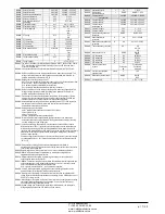
Additional resources
The expansion modules provide additional resources that can be used
through the dedicated setup menus.
The setup menus related to the expansions are always accessible, even if
the expansion modules are not physically fitted.
Since it is possible to add more than one module of the same typology (for
instance two communication interfaces), the setup menus are multiple,
identified by a sequential number.
The following table indicates how many modules of each group can be
mounted at the same time. The total number of modules must be less or
equal than 4.
Дополнительные ресурсы
Модули расширения обеспечивают дополнительные ресурсы, доступ к
которым можно получить через специальные меню настройки.
Меню настройки для модулей расширения доступны всегда, даже когда
физически модуль расширения не установлен.
Поскольку модулей расширения одной и той же топологии можно
установить несколько (например, два интерфейса связи), меню настройки
также может быть несколько – они обозначены порядковым номером.
В следующей таблице указано, сколько модулей каждой группы возможно
установить одновременно. Общее число модулей не должно превышать 4.
Номер и состояние
дополнительных
ресурсов. В обратном
порядке = активно
Тип модулей
расширения
Number and state of
additional resources In
reverse = active
Type of expansion
modules
ЧП
«
Профиэлектро
»
Т
. +380 44 361-62-55, 80
e-mail: [email protected]
www. profielectro.net.ua


