


p. 25 / 39
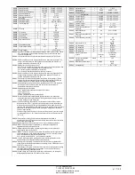
Note: this menu is divided into 4 sections for the analog outputs AOU1...AOU4
available with EXP1005 expansion modules
P23.n.01
-
Specifies the type of output analog signal. The sensor should be connected to the
appropriate terminal on the basis of the type selected. See analog output module
manual.
P23.n.02
- Measurement on which the analog output value depends.
P23.n.03
– If the reference measurement is an internal multichannel measurement (AINx for
example), the channel is defined.
P23.n.04
and
P23.n.05
- Define the value of the measurement that corresponds to a min.
output value in the range (0mA, 4mA, 0V, -5V, etc.).
P23.n.06
and
P23.n.07
- Define the value of the measurement that corresponds to a max. value
in the range (20ma, 10V, +5V, etc.).
Application example: The analog output AOU2 must emit a 0..20mA signal proportional to tha
total active power, form 0 to 500kW.
So, we must program section 2 of this menu, that is referred to AOU2.
P23.2.01 = 0…20mA
P23.2.02 = kW tot
P23.2.03 = 1 (not used)
P23.2.04 = 0
P23.2.05 = x1
P23.2.06 = 500
P23.2.07 = x1k
Примечание. Это меню состоит из 4 частей для аналоговых выходов
AOU1...AOU4, доступных с модулями расширения EXP1005
P23.n.01
–
Определяет тип выходного аналогового сигнала. Датчик должен быть
подключен к соответствующему контакту в зависимости от выбранного типа. См.
руководство к модулю аналоговых выходов.
P23.n.02
– Измерение, от которого зависит значение аналогового выхода.
P20.n.03
– Если контрольное измерение является внутренним многоканальным
измерением (например, AINx), то определяет канал.
P23.n.04
и
P23.n.05
– Определяют значение измерения, соответствующее мин.
выходному значению в диапазоне (0 мА, 4 мА, 0 В, -5 В и т.д.).
P23.n.06
и
P23.n.07
– Определяют значение измерения, соответствующее макс.
значению в диапазоне (20 мА, 10 В, +5 В и т.д.).
Пример применения: Аналоговый выход AOU2 должен выдавать сигнал 0..20 мА,
пропорциональный общей активной энергии от 0 до 500 кВт.
Итак, необходимо задать параметры в разделе 2 этого меню, то есть AOU2.
P23.2.01 = 0…20 мА
P23.2.02 = kW tot
P23.2.03 = 1 (не используется)
P23.2.04 = 0
P23.2.05 = x1
P23.2.06 = 500
P23.2.07 = x1k
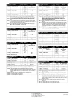
M24 – PULSES
(PULn, n=1…6)
UoM
Default
Range
P24.n.01
Pulse source
OFF
OFF-Kwh-kvar-kVA
P24.n.02
Counting unit
100
10/100/1k/10k
P24.n.03
Pulse duration
s
0.1
0.1-1.00
Note: this menu is divided into 6 sections, for the generation of energy consumption
pulse variables PUL1…PUL6.
P24.n.01
- Defines which energy meter should generate the pulse of the 6 possible meters
managed by the DCRG8.
kWh =
Active energy.
Kvarh
= Reactive energy.
kVA
=
Apparent energy.
P24.n.02
- The quantity of energy which must accumulate for a pulse to be emitted (for example
10Wh, 100Wh, 1kWh, etc.).
P24.n.03
= Pulse duration.
Application example: For every 0,1 kWhoutput by generator, a pulse of 100ms ha sto be
generated on output OUT10.
First of all we should generate an internal pulse variable, forinstance PUL1. So we must
program section 1 of this menu as follows:
P24.1.01 = kWh G (active energy)
P24.1.02 = 100Wh (correspond to 0,1 kWh)
P24.1.03 = 0,5
Now we must set output OUT10 and link it to PUL1:
P04.10.01 = PULx
P04.10.02 = 1 (PUL1)
P04.10.03 = NOR
M24 – PULSES
(PULn, n=1…6)
Ед.
изм.
По ум.
Диапазон
P24.n.01
Источник импульсов
ВЫКЛ.
ВЫКЛ.-Квт*ч-квар-кВА
P24.n.02
Единица отсчета
100
10/100/1k/10k
P24.n.03
Продолжительность
импульса
с
0,1
0,1-1,00
Примечание. Это меню состоит из 6 частей для генерации переменных
импульсов потребления энергии PUL1…PUL6.
P24.n.01
– Определяет, какой счетчик энергии должен генерировать импульс из 6
возможных счетчиков, управляемых устройством DCRG8.
кВт*ч =
активная
энергия.
Квар*ч
= реактивная энергия.
кВА
= видимая энергия.
P24.n.02
– Количество энергии, которую необходимо накопить для получения импульса
(например, 10 Вт*ч, 100 Вт*ч, 1 кВт*ч и т.д.).
P24.n.03
= Продолжительность импульса.
Пример применения:
На каждые 0,1 кВт*ч, выдаваемые генератором, на выход OUT10
необходимо подавать импульс длительностью 100мс.
Сначала необходимо сформировать переменную внутреннего импульса, например,
PUL1.
Итак, необходимо задать параметры в разделе 1 этого меню следующим
образом:
P24.1.01 = kWh G (активная энергия)
P24.1.02 = 100Wh (соответствует 0,1 кВт*ч)
P24.1.03 = 0,5
Теперь необходимо задать выход OUT10 и связать его с PUL1:
P04.10.01 = PULx
P04.10.02 = 1 (PUL1)
P04.10.03 = NOR
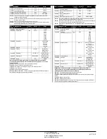
M25 – USER ALARMS
(UAn, n=1…8)
UoM
Default
Range
P25.n.01
Alarm source
OFF
OFF-INPx-OUTx-LIMx-
REMx
P25.n.02
Channel number (x)
1
1-8
P25.n.03
Text
UAn
(testo – 20 char)
Note: this menu is divided into 8 sections for user alarms UA1...UA8
P25.n.01
- Defines the digital input or internal variable that generates the user alarm when it is
activated.
P25.n.02
- Channel number x with reference to the previous parameter.
P25.n.03
- Free text that appears in the alarm window.
Example of application: User alarm UA3 must be generated by the closing of input INP5, and
must display the message ‘Panel door open’.
In this case, set the section of menu 3 (for alarm UA3):
P25.3.01 = INPx
P25.3.02 = 5
P25.3.03 = ‘Door open’
M25 – USER ALARMS
(UAn, n=1…8)
Ед.
изм.
По ум.
Диапазон
P25.n.01
Источник аварийного
сигнала
ВЫКЛ.
ВЫКЛ.-INPx-OUTx-LIMx-
REMx
P25.n.02
Номер канала (x)
1
1-8
P25.n.03
Текст
UAn
(текст – 20 символов)
Примечание. Это меню состоит из 8 частей для пользовательских аварийных
сигналов UA1...UA8
P25.n.01
– Определяет цифровой вход или внутреннюю переменную, создающую
пользовательский аварийный сигнал, если параметр активирован.
P25.n.02
– Номер канала x с учетом предыдущего параметра.
P25.n.03 –
Произвольный текст, выводимый в окне аварийных сигналов.
Пример применения:
Необходимо сформировать пользовательский аварийный сигнал
UA3 при замыкании входа INP5 с выводом сообщения «Panel door open» (Дверь панели
открыта).
В этом случае настройки задаются в разделе 3 меню (для аварийного сигнала UA3):
P25.3.01 = INPx
P25.3.02 = 5
P25.3.03 = ‘Door open’
ЧП
«
Профиэлектро
»
Т
. +380 44 361-62-55, 80
e-mail: [email protected]
www. profielectro.net.ua


