


p. 9 / 39
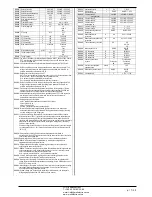
MODULE TYPE
CODE
FUNCTION
MAX Nr.
ADDITIONAL STEPS
EXP 10 06
2 RELAY STEPS
4
EXP 10 01
4 STATIC STEPS
(FAST)
2
COMMUNICATION
EXP 10 10
USB
2
EXP 10 11
RS-232
2
EXP 10 12
RS-485
2
EXP 10 13
Ethernet
1
EXP 10 14
Profibus® DP
1
EXP10 15
GSM-GPRS
1
DIGITAL I/O
EXP 10 00
4 INPUTS
2
EXP 10 02
2
2 ST. OUTPUTS
4
EXP 10 03
2 C/O
RELAYS
4
ANALOG I/O
EXP 10 04
2 ANALOG
INPUTS
2
EXP 10 05
2 ANALOG
OUTPUTS
2
EXP 10 16
CAPACITOR
HARMONIC
PROTECTION
4
ТИП МОДУЛЯ
КОД
ФУНКЦИЯ
МАКС.
КОЛ-ВО
ДОПОЛНИТЕЛЬНЫЕ
СТУПЕНИ
EXP 10 06
2 РЕЛЕЙНЫХ
СТУПЕНИ
4
EXP 10 01
4 СТАТИЧЕСКИХ
СТУПЕНИ
(БЫСТРО)
2
МОДУЛЬ СВЯЗИ
EXP 10 10
USB
2
EXP 10 11
RS-232
2
EXP 10 12
RS-485
2
EXP 10 13
Ethernet
1
EXP 10 14
Profibus® DP
1
EXP10 15
GSM-GPRS
1
ЦИФРОВЫЕ ВХОДЫ-
ВЫХОДЫ
EXP 10 00
4 ВХОДА
2
EXP 10 02
2 ВХОДА +
2 ВЫХОДА
СТУПЕНИ
4
EXP 10 03
2
ПЕРЕКЛЮЧАЮЩИХ
РЕЛЕ
4
АНАЛОГОВЫЕ
ВХОДЫ-ВЫХОДЫ
EXP 10 04
2 АНАЛОГОВЫХ
ВХОДА
2
EXP 10 05
2 АНАЛОГОВЫХ
ВЫХОДА
2
EXP 10 16
ЗАЩИТА
КОНДЕНСАТОРА
ОТ
ГАРМОНИЧЕСКИХ
ИСКАЖЕНИЙ
4
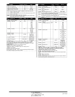
Communication channels
The DCRG8 supports a maximum of 2 communication modules, indicated
as COMn. The communication setup menu is thus divided into two sections
(n=1 … 2) of parameters for the setting of the ports.
The communication channels are completely independent, both for the
hardware (physical interface) and for the communication protocol.
The two channels can communicate at the same time.
Activating the Gateway function it is possible to use a DCRG8 with both an
Ethernet port and a RS485 port, that acts as a bridge over other DCRGs
equipped with RS-485 only, in order to achieve a more economic
configuration (only one Ethernet port).
In this network, the DCRG with Ethernet port will be set with both
communication channels (two among COM1, COM2 and and COM3) with
Gateway
function set to ON, while the other DCRGs will be configured
normally with
Gateway
= OFF.
Каналы связи
Устройство DCRG8 поддерживает не более 2 модулей связи, обозначенных
как COMn. Следовательно, меню настройки связи разделено на две группы
(n=1 … 2) параметров настройки портов.
Каналы связи полностью независимы, как аппаратно (физический
интерфейс), так и по протоколу связи.
Обмен данными возможен по двум каналам параллельно.
При активации режима Gateway (Шлюз), устройство DCRG8 можно
использовать с портом Ethernet и портом RS485 в качестве моста для
других устройств DCRG, оснащенных только портом RS-485. Такой режим
позволит добиться более экономичной конфигурации (только один порт
Ethernet).
В сети такого типа на устройстве DCRG с портом Ethernet настраиваются
оба канала связи (два из COM1, COM2 и COM3) с включенной функцией
Gateway
, а на других устройствах DCRG функция
Gateway
обычно
отключена.
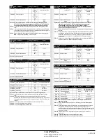
Inputs, outputs, internal variables, counters, analog inputs
The inputs and outputs are identified by a code and a sequence number.
For instance, the digital inputs are identified by code INPx, where x is the
number of the input. In the same way, digital outputs are identified by code
OUTx.
The sequence number of I/Os is simply based on their mounting position,
with a progressive numbering from left to right.
It is possible to manage up to 8 analog inputs (AINx), connected to external
analog sensors (temperature, pressure, flow etc). The value read from the
sensors can be scaled to any unit of measure, visualized on the display
and transmitted on the communication bus. The value read from analog
inputs is shown on the dedicated display page. They can be used to drive
LIMx limit thresholds, that can be linked to an internal or external output.
The expansion I/O numbering starts from the last I/O installed on the base
unit. For example, with OUT1…OUT8 digital outputs on the base unit, the
first digital output on the expansion modules will be OUT9. See the
following table for the I/O numbering:
COD
DESCRIZIONE
BASE
EXP
INPx
Digital Inputs
-
1…8
OUTx
Digital Outputs
1…8
9…16
COMx
Communication ports
-
1…2
AINx
Analog Inputs
-
1…4
AOUx
Analog Outputs
-
1…4
In a similar way, there are some internal bit-variables (markers) that can be
associated to the outputs or combined between them. For instance, it is
possible to apply some limit thresholds to the measurements done by the
system (voltage, current, power, etc.). In this case, an internal variable
Входы, выходы, внутренние переменные, счетчики, аналоговые входы
Входы и выходы обозначаются кодом и порядковым номером. Например,
цифровые входы обозначаются кодом INPx, где x – номер входа.
Аналогичным образом, цифровые выходы имеют обозначение OUTx.
Порядковый номер входов-выходов просто означает их положение
установки с нумерацией слева направо.
В общем, можно управлять 8 аналоговыми входами (AINx), подключенными
к внешним аналоговым датчикам (температуры, давления, расхода и т.д.).
Значение измерения, получаемое от датчиков, может быть выражено
любой единицей измерения, показано на дисплее и передано на шину
связи. Значение, считываемое с аналоговых входов, выводится на
отдельной странице экрана. Для значений можно задать пороговые
пределы LIMx, которые можно коммутировать на внешний или внутренний
выход.
Нумерация входов-выходов модулей расширения начинается с последнего
входа-выхода, заданного на основном устройстве. Например, при наличии
цифровых выходов OUT1…OUT8 на основном устройстве, первым
цифровым выходом модуля расширения будет OUT9. Нумерация входов-
выходов представлена в следующей таблице:
КОД
ОПИСАНИЕ
БАЗА
EXP
INPx
Цифровые входы
-
1…8
OUTx
Цифровые выходы
1…8
9…16
COMx
Порты связи
-
1…2
AINx
Аналоговые входы
-
1…4
AOUx
Аналоговые выходы
-
1…4
Подобным образом, имеются некоторые внутренние битовые переменные
(маркеры), которые можно связать с выходами или объединить друг с
другом. Например, к измерениям, выполняемым системой (напряжение,
сила тока, мощность и т.д.), можно применить некоторые пороговые
пределы. В этом случае каждый раз, когда измерение будет выходить за
ЧП
«
Профиэлектро
»
Т
. +380 44 361-62-55, 80
e-mail: [email protected]
www. profielectro.net.ua


