


p. 13 / 39
master or slave), such as temperature or harmonics protection, then only
outputs that control the steps involved in the panel in alarm are de-
energized, while the rest of the system continues to work, even if with a
limited efficiency.
Each alarm has a specific property called
Slave disconnection
that
indicates if the alarm has implications for the entire system (property set to
General
) or only on the picture concerned (
Local
). See the table of alarms.
(ведущее или подчиненное), например, срабатывает защита по
температуре или гармоникам, то отключаются только те выходы, работа
которых нарушена вследствие аварийного сигнала, а остальные выходы
системы продолжают работать, пусть и при ограниченной эффективности.
Каждый аварийный сигнал имеет определенное свойство
Slave
disconnection (Отключение подчиненного устройства)
, которое
обозначает последствия аварийного сигнала для всей системы (свойство
General
) или только для отдельной ее части (
Local
). См. таблицу аварийных
сигналов.
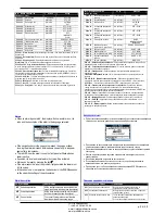
IR programming port
The parameters of the DCRG8 can be configured through the front optical
port, using the IR-USB code CX01 programming dongle, or with the IR-WiFi
code CX02 dongle.
This programming port has the following advantages:
o
You can configure and service the DCRG8 without access to the rear
of the device or having to open the electrical board.
o
It is galvanically isolated from the internal circuits of the DCRG8,
guaranteeing the greatest safety for the operator.
o
High speed data transfer.
o
IP54 front panel.
o
Limits the possibility of unauthorized access with device config.
Simply hold the CX.. dongle up to the front panel, connecting the plugs to
the relevant connectors, and the device will be acknowledged as shown by
the LINK LED on the programming dongle flashing green.
Порт программирования IR
Для настройки прибора DCRG8 на передней панели устройства имеется
оптический порт. Настройка осуществляется с помощью ключа-программатора
IR-USB (код CX01) или ключа IR-WiFi (код CX02).
Порт для программирования имеет следующие преимущества:
o
Настройка и обслуживание устройства DCRG8 без необходимости
получения доступа к задней части устройства или электрической плате.
o
Порт оснащен гальванической изоляцией от внешних цепей прибора.
DCRG8, что гарантирует высочайший уровень безопасности при работе
оператора.
o
Высокая скорость передачи данных.
o
Передняя панель IP54.
o
Ограничение несанкционированного доступа к настройкам устройства.
Просто вставьте ключ CX.. в соответствующий разъем на передней панели, и
устройство будет распознано, о чем будет свидетельствовать мигающий
зеленый светодиод на ключе-программаторе.
USB programming dongle code CX01 Ключ-программатор USB, код CX01
Parameter setting (setup) with PC
You can use the
DCRJ Remote control
software to transfer (previously
programmed) set-up parameters from the DCRG8 to the hard drive of the
PC and vice versa.
The parameter may be partially transferred from the PC to the DCRG,
transferring only the parameters of the specified menus.
The PC can be used to set parameters and also the following:
o
Customised logo displayed on power-up and every time you exit
keyboard setup.
o
Info page where you can enter application information, characteristics,
data, etc.
Настройка параметров с помощью ПК
Для переноса ранее запрограммированных параметров настройки из
устройства DCRG8 на жесткий диск ПК и обратно служит программное
обеспечение
DCRJ Remote control
.
Параметры можно переносить с ПК в устройство DCRG частично, то есть
только параметры указанных меню.
С помощью ПК можно не только настраивать параметры. ПК также позволяет
сделать следующее:
o
Загрузить пользовательский логотип, который будет отображаться при
каждом включении или выходе из режима настройки.
o
Внести информацию о приложении, характеристиках, данных и так
далее на страницу сведений.
ЧП
«
Профиэлектро
»
Т
. +380 44 361-62-55, 80
e-mail: [email protected]
www. profielectro.net.ua


