


p. 5 / 39
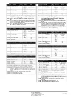
Display page navigation
Keys ▲and ▼scroll through the measurements pages one by one. The
title bar shows the current page.
Some measurements may not be shown depending on the system
programming and connections.
Sub-pages, which can be opened with key ►, are also available on
some pages (displaying voltages and currents in the form of bar graphs,
for example).
The user can specify which page and which sub-page the display should
return to automatically when no keys have been pressed for a certain
time.
The system can also be programmed so the display remains were it was
last.
You can set this function in menu
M01 – Utility
.
Навигация по страницам экрана
Клавиши ▲ и ▼ для перехода по страницам показаний по порядку. Текущая
страница указана в строке заголовка.
В зависимости от программирования системы и подключений некоторые
показания могут не отображаться.
Некоторые страницы (например, с индикацией напряжений и силы тока в
виде гистограмм) имеют вложенные страницы, открываемые с помощью
кнопки ►.
Пользователь может определить страницы и вложенные страницы, которые
будут открываться автоматически при отсутствии нажатий на кнопки в
течение определенного времени.
Систему можно запрограммировать так, что на экране будет всегда
отображаться последняя выбранная страница.
Эту функцию можно настроить в меню
M01 – Utility (Утилиты)
.
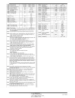
Table of display pages
PAGES
EXAMPLE
Home page)
Power
Voltage and current
Step life statistics
Temperature
Таблица страниц экрана
СТРАНИЦЫ
ПРИМЕР
Главная страница
Мощность
Напряжение и
сила тока
Статистика
продолжительност
и ступени
Температура
Состояние
ступени
Черный =
Вкл.
Серый =
Текущий
CosPhi
Установка
Cosphi
Состояние
вентилятора
Черный =
Вкл.
Серый =
Выкл.
Квар до
достиж-
ения
установки
Гистограм-
ма Квар
Температу-
ра панели
Режим
Aut/Man
Заголовок страницы. Если задано P01.09, то здесь
отображается описание установки.
Заданная
мощность
Измеренная
мощность
Пик макс.
температур с
датой
Порог
аварийног
о сигнала
Гистограмма
с учетом
номинального
напряжения
Гистограмма
с учетом
номинального
тока
Гистограм
-ма с
учетом
TPF = 1,00
Step status
Black = On
Gray = Off
Present
CosPhi
Cosphi
setpoint
Fan status
Black = On
Gray = Off
Kvar
needed to
reach
setpoint
Kvar bar
graph
Panel
temperature
Aut/Man
Mode
Page Title. If P01.09 is set, then the plant
description will be shown here.
Bar graph
referred to
TPF = 1.00
Bar graph
referred to
nominal
voltage
Bar graph
referred to
nominal
current
Set power
Measured
power
Max
temperature
peak with
date
Alarm
threshold
ЧП
«
Профиэлектро
»
Т
. +380 44 361-62-55, 80
e-mail: [email protected]
www. profielectro.net.ua


