background image

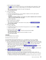
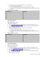
v


No

:


Continue


with


the


next


step.


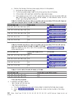
v


Yes

:


Power


regulator


R03


on


FC


5077


expansion


I/O


tower


is


the


failing


item


(see


Type,


model,


and


part


number


list


for


part


number).


4.


Is


the


SRC


1xxC


601A,


671A,


or


673A?


v


No

:


Continue


with


the


next


step.


v


Yes

:


Memory


control


regulator


R03


is


the


failing


item.


All


models


system


unit


-


see


Type,


model,


and


part


number


list


for


part


number.


This


ends


the


procedure.


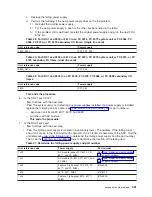
5.


Is


the


SRC


1xxx


1611,


1612,


1613,


1621,


1622


or


1623?


v


No

:


Continue


with


the


next


step.


v


Yes

:


The


Power


regulator


is


the


failing


item.


The


failing


item


is


in


Card


Position


M01


for


a


2


or


4


way


processor


(FC


2400


or


FC


2402)


or


an


8


way


processor


(FC


2403)


(see


Type,


model,


and


part


number


list


for


part


number).

This


ends


the


procedure.


6.


Is


the


SRC


1xxx


1631,


1632,


or


1633?


v


No

:


Continue


with


the


next


step.


v


Yes

:


Power


regulator


3


is


the


failing


item.


The


failing


item


is


in


card


position


M06


-


part


CCIN


2732,


2754,


or


2758.


This


ends


the


procedure.


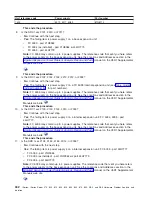
7.


Is


the


SRC


1xxx


6018,


6118,


6518,


6818,


6918,


601A


or


CE18?


v


No

:


Continue


with


the


next


step.


v


Yes

:


Power


regulator


1,


2,


or


3


is


the


failing


item.


Perform


SPCN-PIP1


in


Migrated


Expansion


Tower


Problem


Analysis,


Repair


and


Parts


manual


on


the


V5R1


Supplemental


Manuals


web


site


to


determine


the


failing


item.


The


following


list


shows


the


possible


failing


items


(see


Type,


model,


and


part


number


list


for


part


numbers):


Expansion


I/O


tower


(FC


5077)


System


unit


expansion


(FC


507x)


Storage


expansion


tower


(FC


508x)


This


ends


the


procedure.


8.


Is


the


SRC


1xxx


6x18


or


6x1A?


v


No

:


Continue


with


the


next


step.


v


Yes

:


Power


regulator


1


is


the


failing


item.


Perform


SPCN-PIP1


in


Migrated


Expansion


Tower


Problem


Analysis,


Repair


and


Parts


manual


on


the


V5R1


Supplemental


Manuals


web


site


to


determine


the


failing


item.


The


following


list


shows


the


possible


failing


items


(see


Type,


model,


and


part


number


list


for


part


numbers):


Expansion


I/O


tower


(FC


5077)


System


unit


expansion


(FC


507x)


Storage


expansion


tower


(FC


508x)


This


ends


the


procedure.


9.


Is


the


SRC


1xxx


6x38


or


6x3A?


v


No

:


Continue


with


the


next


step.


v


Yes

:


Power


regulator


2


is


the


failing


item.


Perform


SPCN-PIP1


in


Migrated


Expansion


Tower


Problem


Analysis,


Repair


and


Parts


manual


on


the


V5R1


Supplemental


Manuals


web


site


to


determine


the


failing


item.


The


following


list


shows


the


possible


failing


items:


Analyze


hardware


problems


429

Содержание iSeries Series

Страница 1: ...iSeries iSeries Server 270 800 810 820 825 830 840 870 890 SB2 and SB3 Hardware Problem Analysis and Isolation Version 5 Release 2 SY44 5914 01 ERserver...

Страница 2: ......

Страница 3: ...iSeries iSeries Server 270 800 810 820 825 830 840 870 890 SB2 and SB3 Hardware Problem Analysis and Isolation Version 5 Release 2 SY44 5914 01 ERserver...

Страница 4: ...493 Third Edition August 2002 This edition applies only to reduced instruction set computer RISC systems Copyright International Business Machines Corporation 1998 2002 All rights reserved US Governm...

Страница 5: ...cal partition hangs or loops no SRC 28 Cannot automatically perform an IPL after a power failure 30 Analyze power problems 31 Cannot power on system unit no SRC 31 System or secondary frame cannot be...

Страница 6: ...ce problems 115 INT PIP24 Service processor data collection 115 Licensed Internal Code LIC PIPs 116 LIC PIP1 117 LIC PIP3 118 LIC PIP4 119 LIC PIP7 120 LIC PIP8 123 LIC PIP11 123 LIC PIP12 134 LIC PIP...

Страница 7: ...P1 222 SPCN PIP10 222 SPCN PIP20 222 SPCN PIP21 223 Tape unit PIPs 224 TU PIP1 224 TU PIP2 226 TU PIP3 228 TU PIP4 230 TU PIP6 234 Tape unit self test procedure 235 Tape device ready conditions 237 Tw...

Страница 8: ...CPWR 318 CHECK 319 CLKCARD 320 CLCKCRD 320 CMPRES1 321 CRYPBAT 321 CTLPNCD 322 CTLPNL 323 CVTCARD 324 DCAPWR 324 DEVBPLN 325 DEVICE 325 DEVTERM 325 DIMM 0 326 DIMM0_1 327 DIMM 1 327 DIMM 2 328 DIMM2_3...

Страница 9: ...ion failure 372 MAPPWR 8 Loss of ac power or phase missing 373 MAPPWR 9 2 5 V current voltage problem in processor subsystem 375 MAPPWR A 1 8 V current voltage problem in processor subsystem 378 MAPPW...

Страница 10: ...ROCMM 419 PROCODE 420 PROC0 420 PROC1 420 PROC2 420 PROC3 420 PTFSRCH 420 PWROC 421 PWRREG 425 PWRSPLY 431 QSYSOPR 443 REDH 443 REFER 444 REM_NIC 444 REM_SYS 444 RIOPORT 444 RMDEV 446 SIADPCD 446 SI_C...

Страница 11: ...RPLNR 473 UC235 474 UC236 474 UG3AS 474 UJ0E7 474 UJ6P3 474 UJA34 475 UJE34 475 UJE35 475 UJE40 475 ULNZ3 476 ULNZ4 476 UNP20 476 UPLF1 476 UPSUNIT 476 USER 477 UX201 477 UX202 477 UY1Z1 478 UY1Z2 478...

Страница 12: ...x iSeries iSeries Server 270 800 810 820 825 830 840 870 890 SB2 and SB3 Hardware Problem Analysis and Isolation...

Страница 13: ...or point to additional isolation procedures if available System reference codes SRCs can appear on the control panel the Product Activity Log PAL the Main Storage Dump Manager display or on various di...

Страница 14: ...referring to the Problem reporting page in the Troubleshooting and service topic in Information Center 2 Record the IPL type and mode before starting this service call Note When you complete this serv...

Страница 15: ...system console console of the Primary partition See page 3 v The system is not operational See page 4 v Problem with a secondary partition See page 4 v Problem with a guest partition See page 5 v Tim...

Страница 16: ...nel of an I O expansion tower owned by a secondary partition v You suspect a power problem with resources owned by a secondary partition v There is an IPL problem with a secondary partition and there...

Страница 17: ...e no SAL entries in the Primary partition and no SAL entries in the Hosting partition then contact your next level of support Is the problem appearing in the hosting partition of a guest partition To...

Страница 18: ...iew Replace any hardware FRUs or go to any symbolic FRUs To replace hardware go to Locations and addresses for the model you are working on Note The priority code is the fifth digit of the SRC They ar...

Страница 19: ...the appropriate B600 System reference code table Table 11 You cannot find the symptom in this page Symptom What you should do You cannot find the symptom in this page Note Information about a 940x fra...

Страница 20: ...Handle problems for non critical resources on page 11 This ends the procedure 8 Was the entry isolated does the letter Y appear in the Isolated column v No Go to the System reference code list Use th...

Страница 21: ...nalyze log d On the Select Subsystem Data display select the option to view All Logs Note You can change the From and To Dates and Times from the 24 hour default if the time that the customer reported...

Страница 22: ...10 v Yes Run Analyze Problem option 1 from the Work with Problem display Notes a For SRCs starting with 6112 or 9337 use the SRC and go to the System reference code list b If the message on the displa...

Страница 23: ...procedure v Yes Are there any system operator messages that indicate a communications related problem has occurred No Contact your next level of support This ends the procedure Yes Perform any actions...

Страница 24: ...tem site is too low or too high use a wet dry bulb to check the humidity See General intermittent problem checklist on page 13 for more information v If you need to check ac receptacles for correct wi...

Страница 25: ...not performed correctly Moving of down level hardware from other systems to the iSeries server Incorrectly configured or incorrectly cabled devices v Environment Power line disturbance for example re...

Страница 26: ...hen the system is down go to Starting point for all problems on page 2 Use additional diagnostic tools if necessary and attempt to cause the problem to occur again Note Ensure that the service informa...

Страница 27: ...ed on both ends of all IPI 3 signal cables DFCI cables that leave the frame The ferrite core can be installed up to 15 cm 6 inches from the connector the recommended distance is 8 5 cm 3 4 inches The...

Страница 28: ...this procedure to begin analyzing an intermittent problem 1 Is a reference code associated with the intermittent problem v No Continue with the next step v Yes Go to the System reference code list and...

Страница 29: ...ymptom for the intermittent problem you have is not listed go to Failing area INT PIPs Failing area INT PIPs For use by authorized service providers Use this table only if you do not have a system ref...

Страница 30: ...Table 1 Analyze IPL problems Symptom What you should do You cannot perform an IPL from the system control panel no SRC Go to Cannot perform IPL from the control panel no SRC on page 19 You cannot per...

Страница 31: ...This ends the procedure 3 Have all the units in the system become powered on that you expected to become powered on v Yes Continue with the next step v No Go to Analyze power problems on page 31 and f...

Страница 32: ...m value QIPLDATTIM Description Date and time to automatically IPL IPL date MM DD YY IPL time HH MM SS b On the command line enter the Display System Value command DSPSYSVAL QDATE Check the system valu...

Страница 33: ...he system by entering the Power Down System Immediate command PWRDWNSYS IMMED on the command line c Wait 5 minutes Does the IPL start at the time you specified v No Continue with the next step v Yes T...

Страница 34: ...ed time Note If you exchange the control panel or the SYSBKPL you must set the correct date and time by performing step 4 See page 20 Attention Before exchanging any part power off the system see Powe...

Страница 35: ...ee Power on off the system and logical partitions Continue with the next step v No Perform the following a Change the value to 1 by entering the Change System Value command CHGSYSVAL QRMTIPL on the co...

Страница 36: ...d you verify that the operating system has the correct value of 1 for the remote power on function in step 2 See page 23 v No Continue with the next step v Yes Go to step 9 See page 24 8 On the comman...

Страница 37: ...a Service Tool Hardware Service Manager Work with service action log d On the Select Timeframe display change the From Date and Time to a date and time prior to when the customer reported having the...

Страница 38: ...f the items verify that the item exchanged repaired the problem Notes a See the Failing items on page 249 topic and the Symbolic FRUs topic b When exchanging FRUs go to Remove and replace procedures I...

Страница 39: ...value displayed on the control panel second part of the address for the instruction being executed on processor 0 Notes 1 If the system has multiple processors the preceding steps can be repeated for...

Страница 40: ...ble in the Main Store Dump Summary see iSeries Service Functions Then go to System Reference Codes and use the SRC information to correct the problem This ends the procedure Logical partition hangs or...

Страница 41: ...0 i Select 5103 on the control panel and press Enter Record the value displayed on the control panel second part of the address for the instruction being executed on processor 0 Notes 1 If the system...

Страница 42: ...he Partition Status screen v No Continue with the next step v Yes Go to System Reference Codes and use the SRC information to correct the problem This ends the procedure 7 Did a Missing Disk Units dis...

Страница 43: ...s TM frames will only have the frame number flashing on the failing unit s SPCN card assembly which is visible after removing the cover The system attention light is off function 5 SRCs can exist with...

Страница 44: ...cables from the power supply power distribution unit or external uninterruptible power supply at the customer s ac power outlet connected and seated correctly at both ends v Yes Continue with the nex...

Страница 45: ...r jumper cable part as installed This ends the procedure 9 DANGER Dangerous voltage being measured RSFTD005 Perform the following a Disconnect the mainline ac power cables from the external uninterrup...

Страница 46: ...age 34 v Yes Continue with the next step 13 Is a function 11 SRC displayed on the system unit control panel v No Go to step 15 See page 34 v Yes Go to Starting point for all problems on page 2 This en...

Страница 47: ...ne ac power cables from the ac module or battery charger unit b Use a multimeter to measure the ac voltage at the ac module or battery charger unit end of the mainline ac power cables Continue with th...

Страница 48: ...the DC voltage from 145 V DC to 259 V DC for the battery charger unit or 200 V ac to 240 V ac for the ac module dual line cord v Yes Continue with the next step v No Exchange the battery charger unit...

Страница 49: ...e procedure Is the Power Ready light on continuously Note The Power Ready light blinks at a 1 second rate during a normal power on sequence It should not blink for more than 1 minute v Yes Continue wi...

Страница 50: ...s at the slower one blink per two second rate while powered off and at the faster one blink per second rate during a normal power on sequence It should not blink at the faster rate for more than one m...

Страница 51: ...part as installed This ends the procedure 9 DANGER Dangerous voltage being measured RSFTD005 Perform the following a Disconnect the mainline ac power cables from the external uninterruptible power su...

Страница 52: ...e system b Select the mode on the system unit control panel the customer was using when the power on failure occurred c Attempt to power on the system Does the system power on v Yes Go to step 15 See...

Страница 53: ...y frame Attention To prevent loss of data ask the customer to verify that no interactive jobs are running before you perform this procedure 1 Is the power off problem on a secondary frame with Stage 2...

Страница 54: ...able is powered off or is powering off Does the frame power off v No Continue with the next step v Yes This ends the procedure 7 Ensure there are no jobs running on the system and verify that the batt...

Страница 55: ...ymbolic FRU CTLPNL on page 323 Control panel cable Power controller see symbolic FRU BPCPWR on page 287 Models 870 and 890 only Power VS comm cable Models 870 and 890 only If a secondary frame is fail...

Страница 56: ...rocess If any Power Ready light is blinking for more than 1 minute exchange the power control compartment PCC on the frame with the blinking light Note See the Remove and replace procedures topic or t...

Страница 57: ...nformation in the iSeries TM Service Functions Does the IPL complete successfully v Yes You have corrected the problem Select the mode on the control panel that the customer wants This ends the proced...

Страница 58: ...Repair and Parts information SY44 4934 00 or the Migrated Expansion Tower Problem Analysis Repair and Parts manual on the V5R1 Supplemental Manuals web site depending on the secondary frame you are w...

Страница 59: ...on the secondary frame you are working on A SPCN optical adapter System Unit V J15 J15 J16 J15 Frame J16 J15 Frame Frame J16 J15 Frame 1 2 3 4 Failing frame Continue with the next step 19 Perform the...

Страница 60: ...PCC AC module or SPCN card BKSPCN or TWRCARD in the preceding frame in the string SPCN optical adapter A in the preceding frame in the string SPCN optical adapter B in the failing frame SPCN optical c...

Страница 61: ...ding on pin 2 f Move the positive lead of the multimeter to pin 3 of J16 g Note the voltage reading on pin 3 Is the voltage on both pin 2 and pin 3 from 1 5 V dc to 5 5 V dc v No Exchange the power co...

Страница 62: ...Series TM Server Tower control panel blinking v Yes Continue with the next step v No Go to step 29 See page 50 28 Remove the top cover from the xSeries TM Server Tower Is the two digit display on the...

Страница 63: ...e Migrated Expansion Tower Problem Analysis Repair and Parts manual on the V5R1 Supplemental Manuals web site depending on the secondary frame you are working on v Yes Exchange the AC module See the R...

Страница 64: ...R Dangerous voltage being measured RSFTD005 a Connect the ac power jumper cables to the battery charger unit AC module or power distribution unit b Disconnect the ac power jumper cable at the power su...

Страница 65: ...lowing FRUs v SPCN card see symbolic FRU TWRCARD on page 470 v Power supply see symbolic FRU PWRSPLY on page 431 v System unit card enclosure c Reconnect the mainline ac power cables to the power outl...

Страница 66: ...AC module or SPCN card see symbolic FRU BKSPCN on page 286 for the system or see symbolic FRU TWRCARD on page 470 in the frame from which you removed the SPCN optical adapter See the Remove and replac...

Страница 67: ...ative lead of a multimeter to the system frame ground d Connect the positive lead of the multimeter to pin 2 of the SPCN cable Note Use an insulated probe or jumper when performing the voltage reading...

Страница 68: ...Expansion Tower Problem Analysis Repair and Parts manual on the V5R1 Supplemental Manuals web site depending on the secondary frame you are working on SPCN frame to frame cable AC module or SPCN card...

Страница 69: ...ltage from 200 V ac to 240 V ac or from 100 V ac to 127 V ac v Yes Go to step 9 See page 57 v No Continue with the next step 7 Are you working on a power distribution unit with tripped breakers v Yes...

Страница 70: ...next step 13 Exchange the following parts one at a time v SPCN card unit see symbolic FRU TWRCARD on page 470 v Display unit see symbolic FRU CTLPNL on page 323 v Power supply see Type model and part...

Страница 71: ...system frame ground b Connect the positive lead of a multimeter to pin 2 of J16 in the unit from which you removed the SPCN optical adapter in the previous step of this procedure Notes v If you are w...

Страница 72: ...he secondary unit This ends the procedure v Yes Continue with the next step 25 Perform the following a Power off the system b Disconnect the SPCN frame to frame cable from J15 connector of the first u...

Страница 73: ...the unit string This ends the procedure v No Exchange the SPCN card see symbolic FRU TWRCARD on page 470 from the unit which you disconnected the SPCN cable in the previous step of this procedure See...

Страница 74: ...bus Card gaps may cause system reference codes SRCs that provide incorrect FRU information To determine if there are any card gaps select the Display card gap information function key from the Hardwa...

Страница 75: ...his page Table 1 SRC breakdown SRC word Control panel function Panel function characters Format Description 1 11 1 8 B600 uuuu uuuu unit reference code 69xx 1 extended SRC information 11 9 16 iiii Fra...

Страница 76: ...V5R1 Supplemental Manuals web site Logical card number See the Bus Overview section in the Migrated Expansion Tower Problem Analysis Repair and Parts manual on the V5R1 Supplemental Manuals web site 0...

Страница 77: ...ent FC 5094 towers Table 3 Card positions for Models 270 and 820 Model number Bus number in DSA Multi adapter bridge number in DSA Multi adapter bridge function number in DSA Item DSA points to Positi...

Страница 78: ...IOA CB1 825 001 2 3 Unused CB1 825 001 2 4 PCI IOP or IOA card C06 825 001 2 5 PCI IOP or IOA card C06 825 001 2 6 PCI IOP or IOA card C05 825 001 2 7 PCI IOP or IOA card C05 825 001 2 F Multi adapte...

Страница 79: ...IOA card C06 32 bit xxxx assigned by LIC 1 3 PCI IOP or IOA card C07 32 bit xxxx assigned by LIC 1 4 PCI IOP or IOA card C09 64 bit xxxx assigned by LIC 1 6 PCI IOP or IOA card C10 64 bit xxxx assigne...

Страница 80: ...LIC 2 2 and 3 PCI IOP or IOA card C02 v 001 Models 870 and 890 Base I O Tower only FC 9094 and FC 8094 bottom unit v Otherwise xxxx assigned by LIC 2 4 and 5 PCI IOP or IOA card C03 v 001 Models 870...

Страница 81: ...nd FC 8094 bottom unit v Otherwise xxxx assigned by LIC 2 4 and 5 PCI IOP or IOA card C08 v 0002 Models 870 and 890 Base I O Tower only FC 9094 and FC 8094 bottom unit v Otherwise xxxx assigned by LIC...

Страница 82: ...owers and FC 5078 0578 PCI Expansion Unit for FC 5079 see Servicing notes See page 65 above Bus number Multi adapter bridge number in DSA Multi adapter bridge function number in DSA Item DSA points to...

Страница 83: ...C 1 2 PCI IOP or IOA card C02 64 bit xxxx assigned by LIC 1 4 PCI IOP or IOA card C03 64 bit xxxx assigned by LIC 1 6 PCI IOP or IOA card C04 64 bit xxxx assigned by LIC 1 F Multi adapter bridge CB1 x...

Страница 84: ...2 v Models 830 SB2 840 SB3 870 and 890 See page 73 Table 11 Loop number to NIC port location labels for Models 270 800 810 820 and 825 Decimal loop number Hexadecimal loop number System model NIC s FR...

Страница 85: ...M06 C0 and C1 on the NIC card in position M06 258 0102 840 and SB3 M17 C0 and C1 on the NIC card in position M17 258 0102 Models 870 and 890 M40 A0 and A1 on the NIC card in position M40 259 0103 830...

Страница 86: ...s Models 830 SB2 page For models 840 SB3 see Figure 5 Network Interface Controller NIC port locations in the Locations Models 840 SB3 page Bus PIP procedures Bus PIPs v Bus PIP 1 v Bus PIP 2 v Bus PIP...

Страница 87: ...P processor that you are performing isolation on Follow the instructions for the model you are working on v Models 270 820 830 840 SB2 and SB3 See page 75 v Models 800 810 825 870 and 890 See page 76...

Страница 88: ...Address DSA perform the following a Obtain the bus number by performing one of the following v Record the Direct Select Address DSA which is word 7 from the SAL display The bus number is the 4 leftmo...

Страница 89: ...5R1 Supplemental Manuals web site Follow the instructions to get to the Bus PIP that you were sent there to perform using the migrated tower feature code that you recorded Bus PIP CNSL01 For use by au...

Страница 90: ...r that card location d Power on the secondary partition This ends the procedure 8 The problem is in the Primary partition of a system with one or more partitions Choose from the following options v Fo...

Страница 91: ...RUs should be listed there Look for part numbers and descriptions for the FRUs containing the HSL port for two frames There should also be a FRU for the cable between them The locations information fo...

Страница 92: ...ports on the failed link If the error was cleared up by exchanging the cable go to Verify the repair 6 Exchange the HSL FRU that contains the failing port in the system unit If the error was cleared...

Страница 93: ...your next level of support for further instructions Cannot power on frame v If one or more of the frames in the loop cannot become powered on work the errors related to powering on the frames before...

Страница 94: ...elect Start a service tool Hardware service manager Logical hardware resources High speed link HSL resources 4 Select Include non reporting resources Move the cursor to the HSL loop that you want to e...

Страница 95: ...name that you recorded for the second failed resource j Record the frame ID if present card position and port Record this information for the second failing link in HSL link status diagnosis form k S...

Страница 96: ...source name type model and serial number if it has not been previously recorded 5 Is the status of the Leading port to next resource operational v Yes Select Follow leading port Then continue with the...

Страница 97: ...connector s screws within 30 seconds of when the cable makes contact with the port Otherwise the link will fail and you must disconnect and reconnect the cable again If the connector screws are not ti...

Страница 98: ...ource information See page 86 procedure below Then return to the procedure that sent you here This ends the procedure Collect the resource information Find the information for the failing HSL I O Brid...

Страница 99: ...face Controller NIC for the loop that you selected 5 Fill in the System and Loop Number in the heading of the HSL Loop Configuration and Status Form In the first row of the table fill in the following...

Страница 100: ...packaging resource s b Compare the frame ID on the display with the frame ID in hexadecimal format that you are looking to find Ignore leading zeros c Are the frame IDs the same v No Select Cancel to...

Страница 101: ...ocedure If the label is part of the information for the Leading port then select Follow leading port If the label is part of the information for the Trailing port then select Follow trailing port d Pe...

Страница 102: ...not IPLed will it IPL to DST v No Perform Bus PIP IOP 03 on page 92 This ends the procedure v Yes From the SAL display for the SRC record the count Continue with the next step 2 Go to the SST DST disp...

Страница 103: ...rting point for all problems on page 2 and work that SRC If there was no SRC go to Verify the repair If there were multiple failed IOAs and concurrent maintenance did not work on one then move to the...

Страница 104: ...tion Listing the card position table for the frame type that you recorded the bus number and the multi adapter bridge number to determine the PCI bridge set where the failure occurred Refer to the Car...

Страница 105: ...s and failing items table for the frame type you recorded FRU locations and failing items tables are in Locations and addresses c Power on the system or partition Does the SRC or failure that sent you...

Страница 106: ...s FRU a FRU that you have already exchanged v No Remove the IOP that you exchanged You will be reinstalling the original IOP later in this procedure Then continue with the next step v Yes Call your n...

Страница 107: ...e 95 Record the card position and the DSA from the card position table for each card position that is controlled by the same multi adapter bridge 5 Look in the service action log SAL see Use the servi...

Страница 108: ...em bus resources display showing the multi adapter bridge and the associated resources 18 Is there another IOP under the multi adapter bridge v No Go to step 21 See page 96 v Yes Go to step 12 See pag...

Страница 109: ...Using the card position table record the PCI bridge set card positions and multi adapter bridge function numbers in the form g Examine the PCI bridge set in the frame and record the information in the...

Страница 110: ...ur v No Power off the system or partition Then continue with the next step v Yes Remove the IOP that you just installed and replace the original IOP in its original position Perform Bus PIP IOP 03 on...

Страница 111: ...r the System Configuration Listing to determine which frame or I O tower contains the failing item From the Hardware Service Manager screen select Logical Hardware Resources System Bus resources Move...

Страница 112: ...11 From the Logical Hardware Resources on System Bus display examine the status of all the resources under the multi adapter bridge looking for a failed resource v To examine the status of the IOAs se...

Страница 113: ...en return to the procedure which sent you here Otherwise continue to examine all the IOP and IOA resources on the bus Have you examined all the IOP and IOA resources under the bus v No Repeat step 13...

Страница 114: ...ors and I O adapters that are failing record the bus number BBBB board bb and card information Cc Continue with the next step v Yes Go to step 10 See page 102 7 Perform the following a Return to the D...

Страница 115: ...e procedure Communications PIP For use by authorized service providers This topic contains the procedure necessary to isolate a communications failure Please heed the following warnings when using thi...

Страница 116: ...ing memory module replace the memory module On multiple card combinations exchange the IOA card before exchanging the IOP card Exchange the failing hardware see the Remove and replace procedures This...

Страница 117: ...termittent problems on the network v A new SRC go to Starting point for all problems on page 2 or ask your next level of support for assistance Work with the customer or your next level of support to...

Страница 118: ...ation If there is more than one SRC logged use an SRC that is logged against the IOP or IOA Is an SRC logged as a result of this IPL Yes Continue with the next step No You cannot continue isolating th...

Страница 119: ...me one that sent you to this procedure v No Continue with the next step v Yes The last device you disconnected is not the failing item a Leave the device disconnected and go to step 7 See page 106 to...

Страница 120: ...Read all safety procedures before servicing the system Observe all safety procedures when performing a procedure Unless instructed otherwise always power off the system or expansion tower where the F...

Страница 121: ...mptoms v Yes Look at the recording and see if the voltage monitor recorded any noise when the failure occurred Did the monitor record any noise when the failure occurred Yes Review with the customer w...

Страница 122: ...at attach the system unit to the expansion unit are seated correctly Note If the failures occur when people are close to the system or machines that are attached to the system the problem may be elect...

Страница 123: ...rator must be connected to a ground point as defined above v The service entrance ground bar must connect to a ground point as defined above v All ground connections must be tight v Check continuity o...

Страница 124: ...ning representative or an electrician when necessary perform the following steps 2 Power off the iSeries system and the power network branch circuits before performing this procedure 3 Read Electrical...

Страница 125: ...v Yes Contact the customer to have the voltage source returned to within the normal voltage range 14 The remainder of this procedure is only for an iSeries system that is attached to a separately deri...

Страница 126: ...ound through a tunnel through a covered outside hallway or through a skyway Station protectors help prevent electrical noise on these cables from affecting the iSeries server 1 Look at the Product Act...

Страница 127: ...y method defined as follows v If this SRC is displayed in the system error log then record all of the SRC data words save all of the error log data and contact your next level of support to submit an...

Страница 128: ...ms How often the intermittent problem occurs System environment IPL certain applications If necessary other SRCs that you suspect relate to the problem Information needed to write an LICTR see Authori...

Страница 129: ...the problem To determine if the system has logical partitions go to Determine if the system has logical partitions before continuing with this procedure 2 Is the system operational Did the SRC come fr...

Страница 130: ...ST or SST Obtain the data in steps 3 See page 117 4 See page 117 5 See page 117 and 6 See page 117 14 Provide the dumps to IBM R Service Support This ends the procedure 15 Has the system stopped with...

Страница 131: ...is in the Primary partition exchange the first workstation I O processor card on bus 1 see Remove and replace procedures If the problem is in the secondary partition exchange the I O processor card f...

Страница 132: ...tem has logical partitions perform this procedure from the logical partition that reported the problem To determine if the system has logical partitions go to Determine if the system has logical parti...

Страница 133: ...ng a Use the full authority password to sign on to DST b Search All logs in the product activity log looking for references of SRC B600 5209 and the SRC that sent you to this procedure Note Search onl...

Страница 134: ...s Perform the following a Power off the system b Install the IOP card you just removed c Go to Bus PIP1 on page 75 This ends the procedure 15 Perform the following a Power off the system b Exchange th...

Страница 135: ...occur or does a different URC appear on the console v No Select Perform an IPL on the IPL or Install the System display to complete the IPL Is the problem intermittent Yes Continue with the next step...

Страница 136: ...eries TM Service Functions 1 Did you enter this procedure because all the devices listed on the Display Missing Units display reached from the Disk Configuration Error Report the Disk Configuration At...

Страница 137: ...icated by an asterisk v Yes Continue with the next step v No This ends the procedure 8 Do all of the disk units that are missing from the configuration have a status of Suspended v Yes Continue with t...

Страница 138: ...e following message appear in the list Unknown load source status v Yes Continue with the next step v No Go to step 17 See page 126 16 Select option 5 press F11 and then press Enter to display the det...

Страница 139: ...hat are attached to the MSIOP failing v Yes Is there more than one controller attached to the MSIOP Yes Go to step 24 See page 127 No Go to step 23 See page 127 v No Continue with the next step 27 Are...

Страница 140: ...t by type model serial number or address given in words 4 7 see Service Reference Code SRC Information in the iSeries TM Service Functions 2 See the service information for the specific storage device...

Страница 141: ...ntry 432x 102E 660x 102E 671x 102E see System Reference Codes 9337 7xx0 8xx0 Dxx0 Exx0 x can be a number from 0 through 8 This ends the procedure 000D The system disk capacity has been exceeded For mo...

Страница 142: ...ource disk unit is in device location 1 This ends the procedure 0019 One or more disk units were formatted incorrectly The system will continue to operate normally However it will not operate at optim...

Страница 143: ...eded to update the system configuration are missing Perform an IPL by doing the following 1 Select Manual mode on the control panel 2 Perform an IPL see Initial Program Load IPL Information in the iSe...

Страница 144: ...t Manual mode and perform an IPL to DST see Performing an IPL to DST in the iSeries TM Service Functions information 2 When prompted enter the correct system password If the correct system password is...

Страница 145: ...if the time that the customer reported having the problem was more than 24 hours ago 4 Use the defaults on the Select Analysis Report Options display by pressing Enter 5 Search the entries on the Log...

Страница 146: ...stem Service Tools command If you cannot get to SST use function 21 to get to DST See Dedicated Service Tools DST in the iSeries Service Functions Do not IPL the system to get to DST b On the Start Se...

Страница 147: ...e action log on page 7 This ends the procedure 5 Did you enter this procedure because there was a B6xx 5094 cause code of 0030 v No Continue with the next step v Yes Work with the customer to recover...

Страница 148: ...d disk units have device parity protection disabled when the system expected device parity protection to be enabled 1 Select Manual mode and perform an IPL to DST See Dedicated Service Tools DST in th...

Страница 149: ...ST in the iSeries Service Functions information 2 Correct the problem by doing the following a Select Work with disk units Work with disk unit recovery Recover from start compression failure b Follow...

Страница 150: ...dure direct you to IPL or Power Off the system perform a Main Store Dump or Function 03 IPL if additional dump information is not needed 1 If the system has logical partitions perform this procedure f...

Страница 151: ...step v Yes Go to step 21 See page 141 9 Is the disk unit reference code 0000 v Yes Determine the IOP type by using characters 9 12 of the bottom 16 character line of function 13 4 leftmost characters...

Страница 152: ...the disk unit reference code This ends the procedure v Yes Continue with the next step 15 The disk unit has device parity protection Perform the following a Perform function 3 to IPL the system to DST...

Страница 153: ...racters 1 8 of the top 16 character line of function 13 word 6 contains the disk unit address v Characters 9 16 of the top 16 character line of function 13 word 7 contain the IOP direct select address...

Страница 154: ...s number of one or more units so that each address switch displays the correct number see the system configuration list e For each unit that had its address switch changed set the unit Power switch of...

Страница 155: ...Function 26 and press Enter 4 Select Function 67 and press Enter to reset the IOP 5 Select Function 25 and press Enter to disable the service functions on the control panel 1 From the SST DST screen s...

Страница 156: ...ccept the load source disk unit Go to SST DST in the current partition and select Work with system partitions Recover configuration data Accept load source disk unit This ends the procedure No Power o...

Страница 157: ...than the previous setting v Has the system serial number been changed v Was the load source disk unit in this secondary partition replaced intentionally with a load source from another system or anoth...

Страница 158: ...n and select Work with system partitions Recover configuration data Clear non configured disk unit configuration data b Select the former load source mirror in the list and press Enter 15 Is the Prima...

Страница 159: ...o prevent a possible electrical shock from touching two surfaces with different electrical grounds use one hand when possible to connect or disconnect signal cables RSFTD004 DANGER To prevent a possib...

Страница 160: ...ing paths to start Hyperterminal v Select Start Programs Accessories Hyperterminal v Select Start Programs Communications Hyperterminal 7 Is the Hyperterminal present v Yes Continue with the next step...

Страница 161: ...is no connectivity and you should replace each of the following items one at a time and repeat this test v Operations Console cable P N 97H7557 v 2745 IOA v 2771 IOA 22 If replacing the IOA did not fi...

Страница 162: ...he Power or a Mode indicator green Yes The console may not have control at this time and the remote control panel may be in read only mode Get control at the console and try an operation again If the...

Страница 163: ...lready being used Word 18 contains the card position Disconnect the active communications session and try using the resource again This ends the procedure 6 Are words 13 14 and 15 all equal to 0000000...

Страница 164: ...system or expansion tower where the FRU is located see Power on off the system and logical partitions before removing exchanging or installing a field replaceable unit FRU DANGER To prevent a possibl...

Страница 165: ...is inserted and select Manual mode on the control panel b Select function 21 Make DST Available on the control panel c Press Enter d Enter the password on the DST Sign On display You need the customer...

Страница 166: ...del 270 with a 7104 system unit expansion attached disconnect both the system unit line cord and the expansion unit line cord b Disconnect all the I O devices tape diskette optical and disk units from...

Страница 167: ...e system Does a power reference code occur v Yes Have you disconnected all the cards No Repeat this step Yes Install all parts removed in this procedure and go to Starting point for all problems on pa...

Страница 168: ...ends the procedure v Yes The power supply is functioning normally Continue with the next step 3 Perform the following a Disconnect the ac power cable from the unit you are working on On a system Mode...

Страница 169: ...Perform the following a Power off the system b Disconnect one of the cards you reinstalled in the previous step c Power on the system Does a power reference code occur v No Exchange the last card you...

Страница 170: ...llowing a Disconnect all the I O devices tape diskette optical and disk units from the unit you are working on by sliding them partially out of the unit see the Remove and replace procedures b Remove...

Страница 171: ...his ends the procedure 8 Perform the following a Power off the system b Remove one of the power supplies that was not previously removed in this procedure and replace it with the new one c Power on th...

Страница 172: ...cted in step 13 See page 160 c Power on the system Does a power reference code occur v Yes Have you disconnected all of the I O devices No Repeat step 14 See page 160 Yes This ends the procedure v No...

Страница 173: ...AC modules Does a power reference code occur v No Continue with the next step v Yes Go to step 5 See page 161 4 Perform the following a Power off the frame or system that you are working on Frames wit...

Страница 174: ...was removed in step 6 See page 162 in the original location c Repeat step 6 See page 162 8 Perform the following a Remove the power cable from one of the lower DASD backplanes that was not previously...

Страница 175: ...Power off the frame or system that you are working on Frames with an FC 5078 or FC 0578 attached trace and remove the lower frame power supply ac jumper cables at the AC input battery charger or at th...

Страница 176: ...step 12 See page 165 3 Perform the following a Power off the unit you are working on Units with an FC 5088 or FC 0588 attached trace and remove the lower unit power supply ac jumper cables at the pow...

Страница 177: ...ached trace and remove the lower unit power supply ac jumper cables at the power supplies b Install the AMD that was removed in step 6 See page 165 in the original location c Go to step 6 See page 165...

Страница 178: ...es tape diskette or disk units that you disconnected in step 2 of this procedure c Power on the unit you are working on Units with an FC 5088 or FC 0588 attached reconnect the lower unit power supply...

Страница 179: ...a power reference code occur v Yes Continue with the next step v No Go to step 9 See page 168 3 Perform the following a Power off the system b Remove power supply PP2 c Power on the system Does a powe...

Страница 180: ...M05 b Reconnect the ac power cable to the unit that you are working on c Power on the system Does a power reference code occur v No Continue with the next step v Yes Exchange the last card that you r...

Страница 181: ...it on the new power supply d Install the new power supply P01 e Power on the frame by reconnecting the ac power cables to the unit that you are working on Does a power reference code occur v Yes Conti...

Страница 182: ...Install power supply P01 d Replace the following FRUs one at a time v Control panel see symbolic FRU CTLPNL on page 323 v PCI backplane assembly location CB1 see symbolic FRU TWRCARD on page 470 This...

Страница 183: ...g item This ends the procedure 5 Perform the following a Power off the frame that you are working on by removing the line cords at the FC 5078 FC 0578 FC 5088 and FC 0588 power supplies b Remove the n...

Страница 184: ...llowing a Power off the frame that you are working on by removing the line cords at the FC 5078 FC 0578 FC 5088 and FC 0588 power supplies b Reinstall one of the cards that you removed in step 2 See p...

Страница 185: ...o Perform the following a Power off the system b Install the AMD that was removed in step 4 See page 173 in the original location c Repeat step 4 See page 173 v Yes Install all the AMDs and continue w...

Страница 186: ...t step v No Exchange the last card you disconnected in this step see Remove and replace procedures This ends the procedure 12 Have you disconnected all the cards v No Repeat step 11 See page 174 v Yes...

Страница 187: ...correct the problem perform this procedure until you can power on the system The following steps are for the system unit unless other instructions are given Read the Power PIPs on page 152 for importa...

Страница 188: ...s found 1510 P01 1520 P02 1530 P03 Table 2 Failing power supply for Model 825 See Locations Model 825 Reference code Position 00AC Replace P01 P02 until the failing unit is found 1510 P01 1520 P02 Tab...

Страница 189: ...he failing unit is found 1500 P00 1510 P01 1520 P02 1530 P03 Note Do not install power supplies P00 and P01 AC jumper cables on the same AC input module This ends the procedure 6 Perform the following...

Страница 190: ...Expansion I O Tower or Locations FC 5079 Expansion I O Tower SRC 1xxx 1510 the ac jumper cord connected to P01 and the AC module SRC 1xxx 1520 the ac jumper cord connected to P02 and the AC module v F...

Страница 191: ...Figure 2 Dual line cord drawing for an FC 5078 FC 0578 FC 5088 or FC 0588 installed on an FC 5094 or FC 9094 Analyze hardware problems 179...

Страница 192: ...on disconnect the ac line cord from the External Power Connector or ac jumper cord to the power supply b Use a multimeter to measure the ac voltage at the External Power Connector end of the ac line...

Страница 193: ...C Replace P01 P02 until the failing unit is found 1510 P01 1520 P02 Table 9 Failing power supply for FC 5074 FC 5079 dual line cord See Locations FC 5074 Expansion I O Tower or Locations FC 5079 Expan...

Страница 194: ...d correctly at both ends v Yes Is the SRC 1xxx 00AC Yes Continue with the next step No Go to step 5 See page 183 v No Connect the ac line cords correctly at both ends This ends the procedure 2 Is the...

Страница 195: ...del you are working on to determine the location of AC module A03 b Locate the ac line cord that connects to AC module A03 Attention Do not disconnect the other system line cord when powered on c Cont...

Страница 196: ...1520 the ac jumper cord connected to P02 and the AC module v FC 5078 FC 0578 See Locations FC 5078 FC 0578 Expansion I O Tower SRC 1xxx 1510 the ac jumper cord connected to P02 and the AC module SRC...

Страница 197: ...27 V ac v No Exchange the AC module FC 5074 FC 5079 FC 9074 FC 9079 see Locations and addresses FC 5094 or FC 9094 see Type model and part number list for part number This ends the procedure v Yes Per...

Страница 198: ...nect to J15 and J16 on the frame being serviced RSFTD211 Attention Disconnecting the J15 and J16 cables will not prevent the system unit from powering on Read and understand the following service proc...

Страница 199: ...oose from the following options to clean the IPL media v If it is cartridge type optical media for example DVD do not attempt to clean the media v If it is non cartridge type media for example CD ROM...

Страница 200: ...system This ends the procedure 8 Does either the Disk Configuration Error Report the Disk Configuration Attention Report or the Disk Configuration Warning Report display appear on the console v No Loo...

Страница 201: ...e 123 and use cause code 0002 If any of the reference codes are not 0000 go to step 9 See page 188 and use the reference code that is not 0000 Note Use the characters in the Type column to find the co...

Страница 202: ...ep 6 See page 190 5 Does one of the following displays appear on the console v Disk Configuration Error Report v Disk Configuration Attention Report v Disk Configuration Warning Report v Display Unkno...

Страница 203: ...rocedure v No Either a new reference code occurred or the reference code is 0000 There may be more than one problem The original I O card may be failing but it must be installed in the system to conti...

Страница 204: ...its attached to the SCSI bus identified by FI01105 FI01106 or FI01107 are operating correctly See Verification Procedures in the iSeries Service Functions information Note Do not IPL the system to get...

Страница 205: ...Isolate the failing device by doing the following a Power off the system or the expansion tower if it is powered on See Power on off the system and logical partitions b Go to Failing items on page 24...

Страница 206: ...nes associated with the devices you removed in the earlier steps If the device backplane does not fix the problem then you cannot continue isolating the problem Use the original SRC and exchange the f...

Страница 207: ...gical partitions before continuing with this procedure 2 Were you performing an IPL from removable media IPL type D when the error occurred v No Perform an IPL to DST see Performing an IPL to DST in t...

Страница 208: ...orted v Does not match system configuration rules For example there are too many devices that are attached to the bus v Is failing Perform the following a Look at the characters on the control panel D...

Страница 209: ...ies Service Functions information Does an SRC appear on the control panel v No Does either the Disk Configuration Error Report the Disk Configuration Attention Report or the Disk Configuration Warning...

Страница 210: ...devices that are attached to the bus Find the printout that shows the system configuration from the last IPL and compare it to the present system configuration Note Use the unit address and the physi...

Страница 211: ...upport for assistance This ends the procedure v Yes Use the other I O card or device SRCs to correct the problem see System Reference Codes This ends the procedure 4 Did you perform a D IPL to get to...

Страница 212: ...already using dedicated service tools perform an IPL to DST see Performing an IPL to DST in the iSeries Service Functions information If you cannot perform a type A or B IPL perform a type D IPL from...

Страница 213: ...SST See System Service Tools SST in the iSeries Service Functions information v If you cannot enter a command at the console perform an IPL to DST See Performing an IPL to DST in the iSeries Service...

Страница 214: ...itional Information for each entry to record the formatted log information Example There may be an xxxx902F SRC entry in the Product Activity Log if there are more than 10 disk units in the array Cont...

Страница 215: ...tion to record the formatted log information Record the addresses that are not 0000 0000 for all devices listed Continue with the next step v Yes Access the Product Activity Log and display the SRC th...

Страница 216: ...ew disk unit is initialized and formatted the display shows that the status is complete This may take 30 minutes or longer The disk unit is now ready to be added to the system configuration This ends...

Страница 217: ...of this procedure 5 See Locations and addresses and find the diagram of the system unit or the expansion unit Then find the following v The card slot that is identified by the I O card direct select...

Страница 218: ...as logical partitions go to Determine if the system has logical partitions before continuing with this procedure 2 Access SST DST by doing one of the following v If you can enter a command at the cons...

Страница 219: ...ere installed on this I O card Either they were removed concurrently they were removed after an abnormal power off or they have failed Continue with the next step 9 Use the Reclaim IOP cache storage p...

Страница 220: ...adapter this applies to only some 2780 I O adapters See Type 2748 2757 2763 2778 2780 2782 5703 Cache directory card v If the I O adapter is attached to an auxiliary cache I O adapter ensure that the...

Страница 221: ...ter Install the new replacement storage I O adapter with the following parts installed on it Note Label all parts both old and new before moving them v The cache directory card from the original stora...

Страница 222: ...is ends the procedure Yes This ends the procedure 3 Have the I O cards been moved or reconfigured recently v No Ask your next level of support for assistance This ends the procedure v Yes Perform the...

Страница 223: ...down the system normally with the I O adapter in an operational state The I O adapter or disk units can now be returned to the configuration at the beginning of this procedure This ends the procedure...

Страница 224: ...I O adapter is connected to a non operational storage I O adapter Perform the following 1 Ensure that the SCSI cable of the auxiliary cache I O adapter is connected to the last port of the storage I...

Страница 225: ...e FRU is located See Power on off the system and logical partitions before removing exchanging or installing a field replaceable unit FRU DANGER To prevent a possible electrical shock from touching tw...

Страница 226: ...the operation that was being attempted 3 Attempt a recovery by selecting the white button on the control panel to IPL The IPL mode will automatically change to attempt the recovery IPL using a differe...

Страница 227: ...o it is the DSA of the IOP being used when the error occurred IIIIIIII If word 8 is non zero it is the device unit address of the load source device being used when the error occurred DDDDDDDD If word...

Страница 228: ...unction 13 Replace the load source IOP 2108 00300002 IPL command time out The load source device failed to respond to the first storage IOA in the given time The device unit address is in DDDDDDDD wor...

Страница 229: ...replace either the IOP or IOA and retry the IPL If the problem has not been isolated yet plug each card back in one at a time and retry the IPL until the problem returns Try an IPL with that card in a...

Страница 230: ...mbolic FRU BUS1 on page 289 to fix the problem going directly to the correct step for the system model you are working on 2124 The bus unit at the address in IIIIIIII word 7 had a fatal error No error...

Страница 231: ...SRC was displayed If this is a D mode IPL and a device is present but with no media installed this SRC could mask the expected 4607 refcode and 2127 extended refcode Make sure the alternate device ha...

Страница 232: ...mended service action for B1xx 4682 SRC on a Model 825 Value for EEEE Recommended service action 804B 1 Replace the control panel see symbolic FRU CTLPNL on page 323 2 Then IPL the system 3 If the sam...

Страница 233: ...whether the timeout was due to a problem with the IOP with the storage IOA with the load source device unit or with the device interface Use symbolic FRU IPLINTF on page 350 to fix the problem but do...

Страница 234: ...PCN PIP20 SPCN PIP21 on page 223 SPCN PIP1 For use by authorized service providers A power reference code requiring problem isolation has been detected Go to Power PIP11 on page 175 to correct the pow...

Страница 235: ...at a time see Remove and replace procedures a Control panel see symbolic FRU CTLPNL on page 323 b Tower card see symbolic FRU TWRCARD on page 470 c Control panel cable This ends the procedure SPCN PIP...

Страница 236: ...a possible electrical shock from touching two surfaces with different electrical grounds use one hand when possible to connect or disconnect signal cables RSFTD004 DANGER To prevent a possible electr...

Страница 237: ...t step 4 Is the tape unit installed in an FC 5032 removable storage unit v No Are you working on an 8mm tape drive Yes Continue with the next step No Go to step 6 See page 225 v Yes Go to Tape Unit PI...

Страница 238: ...IP2 For use by authorized service providers Use this procedure to perform the 8mm tape drive read self test and hardware self test The write test is performed in TU PIP3 on page 228 Read the Tape unit...

Страница 239: ...tomatically v The three status lights go on to indicate the start of the hardware test Does the read self test end successfully v No Does the tape drive eject the diagnostic cartridge Yes Continue wit...

Страница 240: ...a problem with the data cartridge A total of three permanent errors have occurred with the same data cartridge c If possible continue operations with a new data cartridge Go to TU PIP3 This ends the p...

Страница 241: ...disk by doing the following a Power off the system see Power on off the system and logical partitions b Select IPL type A in manual mode c Power on the system d Go to step 8 See page 229 6 Place the f...

Страница 242: ...or a tape reel is present do not load it until you need it c Continue with the next step of this procedure 3 Verify the following v If the external device has a power switch ensure that it is set to t...

Страница 243: ...2 are examples of storage resource IOPs b Find the Configuration Description name of the tape unit you are attempting to use and then record the Configuration Description names of all tape units that...

Страница 244: ...the Configuration Description name when using WRKHDWRSC STG the Work with Hardware Resources command You can perform an I O processor IOP reset by performing an IPL of the I O processor All devices th...

Страница 245: ...nue with the next step 16 Perform the following a Enter STRSST the Start SST command on the command line b On the Start Service Tools Sign On display type in a User ID with QSRV authority and Password...

Страница 246: ...ice There are several possible causes v The alternate installation device was not correctly defined v The alternate installation device was not made ready v The alternate installation device does not...

Страница 247: ...for the specific alternate installation device to correct the problem Then retry the alternate installation This ends the procedure Yes Retry the alternate installation This ends the procedure v Yes...

Страница 248: ...that time a static test is performed on tape unit electrical components No tape motion occurs during this step v The cartridge load unload test has an approximate duration of 1 and 1 2 minutes During...

Страница 249: ...l unit On line switch is set to the On line position v Control unit Normal Test switch is set to the Normal position v Control unit channel Enable Disable switch is set to the Enable position v Tape u...

Страница 250: ...sure that the power cords for those devices are unplugged before the signal cables are connected or disconnected If possible disconnect all power cords from the existing system before you add or remov...

Страница 251: ...cedure 4 Is the device you are attempting to repair a personal computer PC v No Continue with the next step v Yes PC emulation programs operate and report system to PC communications problems differen...

Страница 252: ...e previously terminated c Power on the system d If a reference code appears on the control panel go to step 10 See page 241 e If no reference code appears repeat steps a through d of this step until y...

Страница 253: ...Continue to perform the IPL This ends the procedure 12 Is the reference code one of the following 0001 0003 0004 0005 0006 0101 0103 0104 0105 0106 5004 5082 B000 D010 or D023 v No Continue with the n...

Страница 254: ...tep 13 See page 241 17 To use the port tester to isolate the problem perform the following DANGER To prevent a possible electrical shock do not use the port tester during electrical storms RSFTD006 v...

Страница 255: ...r from device to device Only one section of cable can be checked at a time See the SA41 3136 Port Tester Use information This ends the procedure 22 The cable network is bad The wires in the cable betw...

Страница 256: ...verter is the failing item See the link protocol converter service information to correct the problem b Exchange the following parts 1 Console 2 Twinaxial workstation IOA 3 The multi adapter bridge Se...

Страница 257: ...procedures before using this section v Power on off the system and logical partitions v Determining a Primary or Alternative Console in the iSeries Service Functions information WS PIP1 Note If the co...

Страница 258: ...panel Does a display appear on the console v No Does the reference code A600 5005 appear on the control panel Yes Continue with the next step No Go to Starting point for all problems on page 2 to corr...

Страница 259: ...is ends the procedure Workstation adapter console PIP For use by authorized service providers This topic contains the procedure necessary to isolate a failure that is detected by the workstation adapt...

Страница 260: ...tition that reported the problem To determine if the system has logical partitions go to Determine if the system has logical partitions 2 Ensure that your workstation meets the following conditions v...

Страница 261: ...iders Use this table to find the field replaceable unit FRU part numbers identified by a failing item code If only a type number is listed go to the Type model and part number list to determine the pa...

Страница 262: ...Tower Problem Analysis Repair and Parts manual on the V5R1 Supplemental Manuals web site FI00062 See FI00060 See page 250 FI00065 See FI00060 See page 250 FI00070 FI00070 indicates that a storage dev...

Страница 263: ...device To locate the alternate load source for the Primary partition on a system that has multiple partitions or locate the alternate IPL load source for a secondary partition see iSeries TM Service F...

Страница 264: ...ng item Use the device type to determine the part FI00122 FI00122 indicates that a reserved IOA port on the IOP is the failing item If the IOP is type 2624 the failing item is type 6146 IOA FI00123 Se...

Страница 265: ...em For the Model 830 840 SB2 and SB3 FI00186 indicates that the optical cable in the top position lower number bus of the SPD optical Bus Driver is the failing item FI00187 FI00187 indicates that the...

Страница 266: ...s expansion adapter is the failing item For Models 830 840 SB2 and SB3 FI00206 indicates that a type 2685 remote SPD optical bus receiver is the failing item Perform Bus PIP1 in the Migrated Expansion...

Страница 267: ...ible failing items see Type model and part number list for part numbers v SPCN unit part SPNLCRD v SPCN unit part 21H6961 if installed v Secondary AC module if installed v For 9251 base I O if install...

Страница 268: ...in the Migrated Expansion Tower Problem Analysis Repair and Parts manual on the V5R1 Supplemental Manuals web site FI00256 This failing item is in a migrated tower See the failing item table for this...

Страница 269: ...s the Primary partition s console is on bus 0001 and the consoles for other logical partitions are determined by the LPAR configuration FI00500 See FI01140 See page 267 FI00580 FI00580 indicates that...

Страница 270: ...the part number FI00616 FI00616 indicates that the 5259 migration data link is the failing item Exchange the 5259 migration data link FI00626 FI00626 indicates that the modem on the failing port is t...

Страница 271: ...ions cable for the part number FI00717 FI00717 indicates that the EIA 232 V 24 non enhanced cable is the failing item Check the communications cable for the part number FI00718 FI00718 indicates that...

Страница 272: ...the V5R1 Supplemental Manuals web site FI00734 This failing item is in a migrated tower See the failing item table for this failing item in the Migrated Expansion Tower Problem Analysis Repair and Pa...

Страница 273: ...dicates that the I O device attached to the tape IOP is the failing item Use the service information of the I O device to continue analyzing the problem FI00856 FI00856 indicates that an active tape I...

Страница 274: ...N 53P2647 For FC 5072 5073 5077 expansion towers use P N 21H7019 For FC 5065 5074 5079 expansion towers use P N 53P2647 For all other towers use P N 59H3745 v 6383 Internal 1 4 inch cartridge drive wi...

Страница 275: ...ber s to replace v 7239 Model 308 External 1 4 inch cartridge tape library refer to the device service information to determine the part number s to replace v 9348 External 1 2 inch reel tape unit Is...

Страница 276: ...s and type of the failing unit see System Reference Code SRC Information in the iSeries TM Service Functions information If one of the following device types is the failing item see the service inform...

Страница 277: ...es Note If the failing item is in a migration tower go to the recovery procedures in the Migrated Expansion Tower Problem Analysis Repair and Parts manual on the V5R1 Supplemental Manuals web site Thi...

Страница 278: ...e FI01140 See page 267 and FI01141 See page 267 FI01109 A backplane or a connection to the backplane may be failing See the symbolic FRU BACKPLN FI01110 FI01110 indicates that the diskette unit is the...

Страница 279: ...cation of the I O processor card see Locations and addresses list 4 Exchange the failing item associated with the IOP address Note Any of the SCSI cables or backplanes between the IOA and the device c...

Страница 280: ...er for the failing item If the system powers on normally or stays powered on after an ac power failure no replacement of parts may be needed Follow the instructions for the model you are working on v...

Страница 281: ...and M41 VPD to CB1 FC 9094 VSCOMM cable 00AC Cable PWR23 See the Power and signal cables page and follow the Models 870 and 890 processor towers link FC 5075 00AC P01 P02 FC 5078 FC 0578 FC 5088 and...

Страница 282: ...e 175 must be performed before replacing parts b Check the error log when reference codes 7412 and 7413 are both logged at the same time If they are replace part CLCKCRD on page 320 v No Continue with...

Страница 283: ...v FC 5074 or FC 5079 single line cord v FC 5074 or FC 5079 dual line cord Power PIP11 on page 175 must be performed before replacing parts v Uninterruptible power supply base unit for FC 5033 FC 5034...

Страница 284: ...7620 7621 AMD B02 7630 7631 AMD B03 7640 7641 AMD B04 Table 5 For Model 825 Attention The replacement fan must be reconnected within 30 seconds of removal of the failing unit or system failure shutdow...

Страница 285: ...2240 Air moving device AMD panel 2241F AMD 1 2242 AMD 2 2244 v AMD 1 if fan 4 is not installed v Distribution Cable part 44H8337 2245 AMD 5 2246 AMD 6A SPD enclosure 2246 AMD 6B PCI enclosure Table 9...

Страница 286: ...nclosure connected to Bus 1 that might cause an interface failure between the service processor and the alternate IPL load source device 1 Check the load source device unit to ensure it is ready 2 Ver...

Страница 287: ...s that is attached to the interface for the alternate IPL load source device 7 Choose from the following options v If you are on a Model 270 or 820 Continue with the next step v If you are on a Model...

Страница 288: ...If the system IPLs past the original error then isolate to the failing device unit If the failure still occurs replace the following FRUs in order one at a time until the problem is resolved See the...

Страница 289: ...rror light amber exclamation mark see figure below on the Integrated xSeries Server IXS Panel If the system error light is on call your Integrated xSeries Server IXS service provider If the system err...

Страница 290: ...NYBUS For use by authorized service providers Any cable card or card enclosure may be causing an IOP detected bus error The IOP that is reporting the problem may not be causing the problem ANYFC For u...

Страница 291: ...s no memory card in slot location M01 then any one of the memory expansion cards on the processor card in location M02 may be the failing item See Locations Models 800 and 810 to identify the location...

Страница 292: ...the cause of the problem See Locations Model 825 to identify the locations type number and remove and replace procedure for the memory cards Table 2 Memory locations for Model 825 Reference code Locat...

Страница 293: ...the memory expansion cards Table 3 Memory locations for Models 870 and 890 Reference code Location of failure B448 x010 memory in location M18 B448 x011 memory in location M24 B448 x012 memory in loc...

Страница 294: ...23F0 23F1 2422 2452 Note Before exchanging any parts verify that the connections to the backplane are secure n a Model 270 M02 22A7 22A8 2423 one way 24A0 Model 270 M02 22AA 22AB 2424 2 way 24A2 Mode...

Страница 295: ...els 800 and 810 choose from the following options Without processor features 7428 7429 and 7430 The processor is embedded on the system unit backplane Exchange the system unit backplane to exchange th...

Страница 296: ...e code SRC address formats Use the address to find the location see Part locations and listings BACKPLN For use by authorized service providers A backplane or a connection to the backplane may be fail...

Страница 297: ...5074 FC 5079 FC 5094 FC 9074 FC 9079 FC 9094 See Type model and part number list FC 5071 FC 5073 FC 5081 FC 5083 Replace the failing charger see Type model and part number list v Internal battery powe...

Страница 298: ...st for part number information Note When the FC 5058 expansion unit is installed on an FC 5071 FC 5073 FC 5081 and FC 5083 the battery power unit 2 is required External battery power unit 2 battery pa...

Страница 299: ...ling item 1 Use the table below to find the part number you need 2 Refer to the Models 870 and 890 Bulk power controller remove and replace procedure Notes v Before replacing any field replaceable uni...

Страница 300: ...xA xx17 BPF A 1xxB xx17 BPF B This ends the procedure BPRPWR For use by authorized service providers The bulk power regulator BPR may be the failing item 1 Use the table below to find the part number...

Страница 301: ...ble or card enclosure connected to bus 1 that might cause an interface failure between the service processor and the system unit processor The system unit or the base I O tower has failed and the diag...

Страница 302: ...23 2424 2454 or a Model 810 system unit with processor features 7428 7429 or 7430 See either Figure 2 Model 270 system unit processor features 22A7 22A8 22AA 22AB 23F4 23F5 2423 2424 2454 in the Locat...

Страница 303: ...B2 and SB3 Perform the following a Power off the system from the control panel b Check cable connections between the system unit and the base I O tower c Reseat cables where possible d Power on the sy...

Страница 304: ...ase I O Tower See Locations Models 870 and 890 with an FC 9094 Base I O Tower Replace the following FRUs in order one at a time until the problem is resolved Be sure to IPL in SLOW OVERRIDE mode after...

Страница 305: ...v Select F8 to move through the loop until you find the link containing the cable you just replaced in the Leading Port or Trailing Port display If the status is operational then changing the cable f...

Страница 306: ...bbon cable connecting the frame to the tower card in position CB1 FC 5078 FC 0578 Expansion I O Unit See Locations FC 5078 FC 0578 Expansion I O Unit External HSL ports on the HSL I O bridge card in p...

Страница 307: ...ext step v No The AMD you removed in this step is the failing item This ends the procedure 4 Have you removed all of the AMDs one at a time v No Perform the following a Install the AMD that was remove...

Страница 308: ...he procedure v No The SPCN card exchanged in this step was the failing item This ends the procedure 10 Perform the following a Power off the system b Install one of the bulk power supplies that was re...

Страница 309: ...Models 800 and 810 Go to symbolic FRU SYSBKPL on page 464 Model 825 Go to symbolic FRU SYSBKPL on page 464 Models 870 or 890 Base I O Tower Go to symbolic FRU TWRPLNR on page 473 FC 5074 FC 5078 FC 0...

Страница 310: ...69 v If no capacitor card is installed in CAP 2 M37 location install one It is required v If a capacitor card is installed in CAP 2 location reseat it If the problem is not fixed replace it v See Type...

Страница 311: ...ollowing parts one at a time Panel backplane to base backplane cable SIG5A if installed part 44H8017 SIG5B if installed part 44H8021 Panel backplane to power supply SIG9A if installed part 44H8016 SIG...

Страница 312: ...t 97H2348 This ends the procedure 9 Is the SRC 1xxx 1512 1522 or 1532 v No Continue with the next step v Yes Exchange one of the following one at a time For all except FC 5078 0578 and FC 5088 or FC 0...

Страница 313: ...8942 or 8943 v Yes Continue with the next step v No Go to Starting point for all problems on page 2 This ends the procedure 14 Reseat the RS485 cable Does this correct the problem Note It may take up...

Страница 314: ...may be failing Replace the cables for that unit until the error is corrected That is if the error is corrected after replacing the first selected cable then this ends the procedure Otherwise continue...

Страница 315: ...Red with white stripe PWR06 1 BPC B J04 to MDA F1 J2 Red PWR07 1 BPC A J05 to MDA F2 J1 Red with white stripe PWR08 1 BPC B J05 to MDA F2 J2 Red PWR01 BPC A J06 to MDA F3 J1 Red with white stripe PWR0...

Страница 316: ...x20D M02 A B C D x20E M02 A B x211 M02 E x212 M02 F x213 M02 G x214 M02 H x21D M02 E F G H x21E M02 C D x221 M02 J x222 M02 K x223 M02 L x224 M02 M x22D M02 J K L M x22E M02 E F x231 M02 N x232 M02 P...

Страница 317: ...ference code and Location Reference code and Location Reference code and Location Reference code and Location x001 MB1 x00A M01 M02 M03 M24 x00B M20 M21 M22 M23 x00C M08 M09 M10 M11 x00D M12 M13 M14 M...

Страница 318: ...NA 25BD 820 0152 0152 NA 25BE 820 23A1 2395 1521 244A 820 23A2 2395 1522 244A 820 23A3 2395 1523 244A 820 23A4 2395 1524 244A 820 23A9 2396 1521 24A0 820 23AA 2396 1522 24A0 820 23AB 2396 1523 23A0 82...

Страница 319: ...20 24AB 2436 1524 25BC 820 24AA 2436 1523 25BC 820 24A9 2436 1522 25BC 820 24A8 2436 1521 25BC 820 249E 2435 1524 25BC 820 249D 2435 1523 25BC 820 249C 2435 1522 25BC 820 249B 2435 1521 25BC 820 243F...

Страница 320: ...D 830 24DA 2349 1533 245D 245D 830 24D9 2349 1532 245D 245D 830 24D8 2349 1531 245D 245D 830 0153 0153 NA 245D 245D 830 26AE 2351 1537 245D 245D 830 26AD 2351 1536 245D 245D 830 26AC 2351 1535 245D 24...

Страница 321: ...C8 2354 1548 246F 246E 246E 246E 840 26C7 2354 1547 246F 246E 246E 246E 840 26C6 2354 1546 246F 246E 246E 246E 840 26C5 2354 1545 246F 246E 246E 246E 840 26C4 2354 1544 246F 246E 246E 246E 840 26C3 23...

Страница 322: ...24C3 2416 1543 245F 245E 840 24C4 2416 1544 245F 245E 840 24C5 2416 1545 245F 245E 840 24C6 2416 1546 245F 245E 840 24C8 2417 1540 245F 245E 245E 840 24C9 2417 1541 245F 245E 245E 840 24CA 2417 1542...

Страница 323: ...er card the location will have a sub card letter for example M02 A where M02 is the card slot and A is the sub card letter This ends the procedure 7 cedure Type number from the FRU information is zero...

Страница 324: ...ion 270 22A2 22A4 22A5 2422 Note The processor is embedded in the system backplane 2249 MB1 270 2301 2302 Note The processor is embedded in the system backplane 224A MB1 270 23E7 Note The processor is...

Страница 325: ...BB 24BC 24BD 24BE 3007 3009 M01 s M02 s or M03 s 830 All 3002 3004 3005 3006 3007 M02 s or M05 s SB2 All 300F M02 s or M05 s Models 830 SB2 and 840 SB3 Model Processor feature code Processor or clock...

Страница 326: ...06 840 SB3 All 2737 2755 2759 2770 M17 Instructions for Models 800 810 825 870 and 890 There is a hardware failure or the system is not able to give configuration or hardware information The following...

Страница 327: ...on for Model 825 Use the following list to determine the failing item given in the SRC Then use the table below to determine the CCIN number of that FRU The following information is included in this l...

Страница 328: ...D3 890 32 w 2AD3 2488 1579 25D3 25D3 25D3 25D3 890 32 w 2AD2 2488 1578 25D3 25D3 25D3 25D3 890 32 w 2AD1 2488 1577 25D3 25D3 25D3 25D3 890 32 w 2AD0 2488 1576 25D3 25D3 25D3 25D3 890 32 w 0198 0198 NA...

Страница 329: ...0 25B9 MB1 800 810 x001 7407 7408 7409 25BA MB1 825 4009 8009 or C009 All 289C 4 way or 289D 6 way Backplane extender right side MB2 825 400A 800A or C00A All 28B3 Backplane extender left side MB1 825...

Страница 330: ...x00A All 2738 M41 CDAWKLD For use by authorized service providers Too many communications lines are in use CDTRAY For use by authorized service providers This symbolic FRU is not supported CECPWR For...

Страница 331: ...ower supply in location PP1 in the 830 system unit c Power supply in location PP2 in the 830 system unit 6 This is a Model 840 SB3 system unit and FC 9079 base I O tower See Locations Models 840 SB3 s...

Страница 332: ...to step 5 See page 321 v If you are on a Model 830 840 SB2 or SB3 Go to step 6 See page 321 v If you are on a Model 870 or 890 Go to step 7 See page 321 2 Is this system a Model 270 system unit with p...

Страница 333: ...es Be sure to IPL in SLOW OVERRIDE mode after each replacement a Clock card in location M19 in the 840 system unit b JTAG cable c Regulator card in location M04 in the 840 system unit d Regulator card...

Страница 334: ...v Models 270 800 and 810 Control panel NB1 v Model 820 Control panel NB1 v Model 825 Control panel NB1 v Model 830 SB2 with FC 9074 System unit control panel NB1 v Model 840 SB3 processor tower FC 80...

Страница 335: ...90 with an FC 9094 Base I O Tower for part number See the following remove and replace procedures before exchanging the control panel v Models 270 800 and 810 Control panel NB1 v Model 825 Control pan...

Страница 336: ...s ends the procedure CVTCARD For use by authorized service providers CVTCARD High speed link I O bridge and SPD conversion hardware The failing item is the HSL I O bridge card in an FC 5033 FC 5034 FC...

Страница 337: ...y the direct select address v The addressed storage device location identified by the device address 4 Exchange the failing device Use the device type to determine the part This ends the procedure DEV...

Страница 338: ...nd DIMM 3 on the 2890 and 2892 Integrated xSeries Server IXS cards Figure 1 Locations of DIMM 0 DIMM 1 DIMM 2 and DIMM 3 on 2890 Integrated xSeries Server IXS card Figure 2 Locations of DIMM 0 DIMM 1...

Страница 339: ...second DIMM from the top DIMM 0 or DIMM 1 of the IXS card is the failing item To determine the part number go to symbolic FRU MEMORY on page 401 This ends the procedure DIMM 1 For use by authorized s...

Страница 340: ...M 2 For use by authorized service providers Use this page to view the locations of DIMM 0 DIMM 1 DIMM 2 and DIMM 3 on the 2890 and 2892 Integrated xSeries Server IXS card Figure 1 Locations of DIMM 0...

Страница 341: ...U MEMORY on page 401 This ends the procedure DIMM2_3 For use by authorized service providers Use this page to view the locations of DIMM 0 DIMM 1 DIMM 2 and DIMM 3 on 2892 Integrated xSeries Server IX...

Страница 342: ...ntegrated xSeries Server IXS cards Figure 1 Locations of DIMM 0 DIMM 1 DIMM 2 and DIMM 3 on 2890 Integrated xSeries Server IXS card Figure 2 Locations of DIMM 0 DIMM 1 DIMM 2 and DIMM 3 on 2892 Integr...

Страница 343: ...are Related System Reference Code Formats in the iSeries Service Functions book The two right most characters of word 2 define the SRC format Use the correct SRC format to locate the function that con...

Страница 344: ...No Go to step 23 See page 335 3 Perform the following a Power off the system b Reinstall one of the Mxx load cards that was removed in step 2 See page 332 c Power on the system Does the system power...

Страница 345: ...cards that was removed in step 10 See page 333 c Power on the system Does the system power on v Yes Continue with the next step v No The last card that was reinstalled in this step is the failing ite...

Страница 346: ...cards that was removed in step 18 See page 334 c Power on the system Does the system power on v Yes Continue with the next step v No The last card that was reinstalled in step 18 See page 334 is the...

Страница 347: ...ng a Power off the system b Remove the new regulator where installed previously and install the original regulator c Repeat step 23 See page 335 v Yes This ends the procedure DPAC For use by authorize...

Страница 348: ...ailing If more than one device is attached they may have duplicate addresses See the device documentation for information on setting the device address Perform the following 1 Find the IOA type a Find...

Страница 349: ...w 2749 3490 Fxx 3570 358x 9427 7208 342 18 0 meters 49G6459 Note For 358x and 9427 see the Notes See page 338 below 2749 63A0 See device documentation to determine cable part numbers 2749 7208 012 720...

Страница 350: ...ds the procedure FCCABLE For use by authorized service providers The Fiber Channel cable may be failing Use the part number on the cable to determine the part number to replace FCCODE For use by autho...

Страница 351: ...FRU in the SRC table This ends the procedure 2 Go to the Product Activity Log Find the most recent 2765 2766 2787 5704 3120 SRC Has a 2765 2766 2787 5704 3140 SRC occurred after the most recent 2765 2...

Страница 352: ...viders Follow the instructions for the model you are working on v Models 270 800 810 and 820 See page 340 v Models 830 and SB2 See page 340 v Models 840 and SB3 See page 340 v Models 825 870 and 890 S...

Страница 353: ...procedure 3 Is the SRC for an xSeries TM Server Tower v No Continue with the next step v Yes Exchange the Integrated xSeries Adapter IXA see Type model and part number list 4 Perform the following to...

Страница 354: ...the ID MUST be powered down with ac applied a Select Function 07 on the system control panel and press Enter An 07 will display b Use the arrow keys to increment decrement to subfunction A9 An 07A9 wi...

Страница 355: ...the next step v No This ends the procedure 6 Perform the following a Power off the system b Exchange the SPCN card in the failing frame see symbolic FRU TWRCARD on page 470 This ends the procedure 7...

Страница 356: ...rm the following a Power off the system b Install one of the units removed in step 8 See page 343 c Power on the system Does the SRC 1xxx 7405 appear on the panel v No Continue with the next step v Ye...

Страница 357: ...ID below Figure 2 Control panel diagram for function A8 Table 3 Configuration ID ID Model 80 FC 5065 FC 5066 81 FC 5074 FC 5079 FC 8079 002 FC 8093 002 82 FC 9079 on Model 840 FC 8079 001 83 FC 9074 o...

Страница 358: ...ur on the panel v Yes Continue with the next step v No This ends the procedure 20 Perform the following a Power off the system b Exchange the SPCN card in the system unit see symbolic FRU TWRCARD on p...

Страница 359: ...splayed Press Enter 07A8 00 will be displayed c Use the arrow keys to increment decrement to the frame address of the box you want to check usually 02 03 for the towers 01 for system unit frames 07nn...

Страница 360: ...le Table 6 Configuration ID ID Model 81 FC 5074 FC 5079 FC 8093 002 84 FC 5078 FC 0578 89 FC 5088 FC 0588 8A FC 5094 FC 5294 8B FC 5095 90 FC 5075 91 Model 800 or 810 without an expansion unit FC 7116...

Страница 361: ...es Go to the next FRU on the list v No Continue with the next step 10 Is the SRC 1xxx 8431 or 1xxx 8441 v No This ends the procedure v Yes Continue with the next step 11 Perform the following a Power...

Страница 362: ...Go to Starting point for all problems on page 2 and follow the service actions for the new SRC This ends the procedure 2 Power off the system from the control panel Attempt to IPL from a different lo...

Страница 363: ...r IOA card Follow the service actions for the new SRC 7 Remove and label all of the storage device units EXCEPT for the alternate IPL load source device unit you are currently using This includes all...

Страница 364: ...ld mean to remove the cards in locations C02 and C04 but leave the cards in location C01 and C03 Attempt to perform the alternate IPL Does the same SRC occur v Yes Continue with the next step v No If...

Страница 365: ...step 15 See page 355 2 Are you working on an FC 5075 FC 0575 FC 5095 or FC 0595 Expansion I O Tower v No Continue with the next step v Yes Go to step 20 See page 356 3 Is the SRC 3100 v No Continue wi...

Страница 366: ...311C v No Continue with the next step v Yes Replace the Tower card CB1 Use the FRU locations and failing components table in the Locations and addresses page for the model or feature code you are work...

Страница 367: ...he HSL I O bridge Use the FRU locations and failing components table in the Locations and addresses page for the model or feature code you are working on The table will include location and remove and...

Страница 368: ...p v Yes Replace the following FRUs one at time Use the FRU locations and failing components table in the Locations and addresses page for the model or feature code you are working on The table will in...

Страница 369: ...e topic v Use the examples there to break down the SRC and extract any values that may be given for the pairs RC02 and TP02 RC03 and TP03 RC04 and TP04 and RC05 and TP05 The TP0x values are hardware C...

Страница 370: ...Unit Backplane in location MB1 See Model 825 System unit backplane MB1 v For Models 870 and 890 the Service Processor is part of the Tower Card in the Base I O Unit in location CB1 See Models 870 and...

Страница 371: ...ated tower Go to symbolic FRU LBSADP4 in the Migrated Expansion Tower Problem Analysis Repair and Parts manual on the V5R1 Supplemental Manuals web site for information on servicing this failing item...

Страница 372: ...er A or B mode Then the secondary partition can IPL in any mode v If the Primary partition is IPL d in mode C then Guest partitions will not IPL For Guest partitions this may be a problem accessing or...

Страница 373: ...these appear in upper case in the console Meaning or corrective action Multi adapter bridge has no IOP for the I O adapters v Step a System code detected one or more I O adapters under the multi adapt...

Страница 374: ...ystem code detected that an I O processor card was located in that card location on the previous IPL The I O processor is no longer installed in that location I O adapter unavailable due to moved I O...

Страница 375: ...another IOP using concurrent maintenance Removal failures v This is a LIC problem and should be reported v Call your next level of support Linux owned slot no IOP is allowed An I O processor card was...

Страница 376: ...it with FC 9074 base I O tower Models 840 and SB3 Base I O Tower FC 9079 Tower card CB1 See Locations for FC 9079 Base I O Tower On Models 840 SB3 system unit Models 870 and 890 Tower card CB1 See Loc...

Страница 377: ...76 or 1xxA FE76 for BPR 3A 1xxB 0856 or 1xxB FE56 for BPR 1B 1xxB 0866 or 1xxB FE66 for BPR 1B 1xxB 0876 or 1xxB FE76 for BPR 1B Go to MAPPWR 2 There is a bulk power regulator BPR communications fault...

Страница 378: ...subsystem on page 388 1xxC 6514 1xxC 6D14 1xxC B514 1xxC BD14 1xxC B544 1xxC BD44 Go to MAPPWR E 5 0 V current voltage problem in processor subsystem on page 392 1xxA x115 1xxA x215 1xxA x315 1xxA x41...

Страница 379: ...ntinue with the next step v No Set the switch to the Normal position and continue the with the next step 2 Press the white Service Complete button Is the error code 101A FE06 or 101B FE06 displayed No...

Страница 380: ...364 introduction before performing this procedure 1 Ensure the following for the Model 870 and 890 system unit v If the room EPO cable is not installed Make sure that the room EPO BYPASS switch on th...

Страница 381: ...m has been corrected See Verify the repair This ends the procedure v Yes Perform the next action on the list If all actions have been performed then call your next level of support for assistance This...

Страница 382: ...of support for assistance This ends the procedure 5 Be sure you are working on the side of the BPA A or B referenced by the error code that sent you to this procedure FRUs on the operating side of th...

Страница 383: ...closure Push the spring loaded door open and hold it open with one hand Using a suitably long instrument a 12 inch ruler or long handled screwdriver push gently against the recirculation flaps at the...

Страница 384: ...em has been corrected Go to Verify the repair This ends the procedure v Yes Continue with the next step 2 Check the position of the on off switch on the BPRs Is the switch in the ON position to the le...

Страница 385: ...check out okay v No The customer must restore utility voltage This ends the procedure v Yes Exchange the line cord and continue with the next step 6 Press the white Service complete button Is the erro...

Страница 386: ...ent you to this procedure See symbolic FRU BPCPWR on page 287 Bulk power enclosure on the side referenced by the error code that sent you to this procedure See Bulk power enclosure assembly Models 870...

Страница 387: ...t location M07 v Memory book 3 at location M02 5 Power on the system See Power on off the system and logical partitions 6 Did the system stop with the same error code as recorded in step 1 See page 37...

Страница 388: ...all the books listed in step 14 See page 376 been reinserted v Yes The symptom has changed Return the system to its original configuration See Verify the repair This ends the procedure v No Go to ste...

Страница 389: ...a time and in the order listed See Locations Models 870 and 890 with an FC 9094 Base I O Tower for a link to the part number and remove and replace procedure a DCA 1 RH at location M31 b DCA 2 RH at l...

Страница 390: ...Yes Continue with the next step v No Replace the DCA that has the amber logic power LED that did not turn off See symbolic FRU DCAPWR on page 324 4 Pull out the following books about 25 mm 1 inch if p...

Страница 391: ...ed out and listed in step 14 See page 379 19 Power on the system See Power on off the system and logical partitions 20 Did the system stop with the same error code as recorded in step 1 See page 378 v...

Страница 392: ...logic power LEDs of all installed processor subsystem DCAs 33 Are all amber logic power LEDs of all installed processor subsystem DCAs off v Yes Continue with the next step v No Replace the DCA that h...

Страница 393: ...location M27 v L3 module at location M28 v L3 module at location M29 v Clock card at location M15 see Models 870 and 890 System clock card 43 Power on the system See Power on off the system and logica...

Страница 394: ...e error code and the location codes that sent you to this procedure 2 Power off the system See Power on off the system and logical partitions Then examine the amber logic power LEDs of all installed p...

Страница 395: ...One of the books just removed is defective a Power off the system See Power on off the system and logical partitions b Make sure all amber logic power LEDs of all installed processor subsystem DCAs a...

Страница 396: ...r This ends the procedure v No Go to step 28 See page 384 32 Power off the system See Power on off the system and logical partitions Then examine the amber logic power LEDs of all installed processor...

Страница 397: ...ule at location M23 v L3 module at location M26 v L3 module at location M27 v L3 module at location M28 v L3 module at location M29 43 Power on the system See Power on off the system and logical parti...

Страница 398: ...n before performing this procedure 1 Record the error code and the location codes that sent you to this procedure 2 Power off the system See Power on off the system and logical partitions Then examine...

Страница 399: ...replaced is defective Return the system to its original configuration See Verify the repair This ends the procedure 17 Power off the system See Power on off the system and logical partitions Then make...

Страница 400: ...les listed in step 22 See page 387 been reinstalled v Yes The symptom has changed Return the system to its original configuration See Verify the repair This ends the procedure v No Go to step 25 See p...

Страница 401: ...ed processor subsystem DCAs are off 8 Reinsert one of the books that is pulled out and listed in step 4 See page 389 9 Power on the system See Power on off the system and logical partitions 10 Did the...

Страница 402: ...that has the amber logic power LED that did not turn off See symbolic FRU DCAPWR on page 324 24 Pull out the following books about 25 mm 1 inch if present Models 870 and 890 Network interface controll...

Страница 403: ...ds the procedure 38 Turn off the power See Power on off the system and logical partitions Then make sure all amber logic power LEDs of all installed processor subsystem DCAs are off 39 Remove the new...

Страница 404: ...efective Return the system to its original configuration See Verify the repair This ends the procedure 56 Power off the system See Power on off the system and logical partitions Then make sure all amb...

Страница 405: ...s 13 Are all amber logic power LEDs of all installed processor subsystem DCAs off v Yes Continue with the next step v No Replace the DCA that has the amber logic power LED that did not turn off See sy...

Страница 406: ...system See Power on off the system and logical partitions b Make sure all amber logic power LEDs of all installed processor subsystem DCAs are off 28 Reinsert one of the books that is pulled out and l...

Страница 407: ...ort Then replace the system backplane at location MB1 See Locations Models 870 and 890 with an FC 9094 Base I O Tower for part number and remove and replace information 43 Power on the system See Powe...

Страница 408: ...D 1A J09 to DCA 5 J00 cable 1xxB x115 BPC B MDA 1 BPC B J04 to MDA 1 J02 cable 1xxB x215 BPC B MDA 2 BPC B J05 to MDA 2 J02 cable 1xxB x315 BPC B MDA 3 BPC B J06 to MDA 3 J02 cable 1xxB x415 BPC B MDA...

Страница 409: ...e with the power cable that was not connected properly to the off right position 13 Wait 30 seconds and then turn the power on switches of the BPRs found in step 12 See page 397 to the on left positio...

Страница 410: ...following FRUs one at a time v UEPO card assembly See the Final assembly Models 870 and 890 v Cable from the UEPO to BPC on the side referenced by the error code that sent you to this procedure See sy...

Страница 411: ...6 MCM 3 at location M14 MAPPWR J There is a bulk power enclosure BPE communication failure For use by authorized service providers Note Read the Danger and caution notices in the MAPPWR on page 364 in...

Страница 412: ...ns Model 820 Model 825 System unit backplane MB1 See Locations Model 825 Models 830 and SB2 base I O tower FC 9074 Tower card CB1 See Locations Models 830 SB2 system unit with FC 9074 base I O tower M...

Страница 413: ...d memory configuration For memory DIMM location information refer to Memory locations and placement rules For system location details refer to the following v For Model 270 See Locations Model 270 v F...

Страница 414: ...ositions DIMM 0 DIMM 1 DIMM 2 or DIMM 3 2 An IXS adapter card IOP see Type model and part number list for part number is required in the IOP DIMM position This IOP memory module is NOT interchangeable...

Страница 415: ...allowed v Cluster and migrated SPD unit v Multiple SPD migrated units v Migrated unit not on loop 256 MOVEIOA For use by authorized service providers An Incorrect hardware configuration was detected T...

Страница 416: ...m the following options v If you are on a Model 270 800 810 or 820 Continue with the next step v If you are on a Model 830 840 SB2 or SB3 Go to step 7 See page 405 4 Is this a Model 270 system unit wi...

Страница 417: ...lace procedures a Memory cards in bank A in the system unit b Memory cards in bank B in the system unit c Memory cards in bank C in the system unit d Memory cards in bank D in the system unit This end...

Страница 418: ...ndows NT Server device driver may be causing the problem Refer to the Windows server on iSeries page which is located in the Networking topic in the Information Center or contact your next level of su...

Страница 419: ...ers The cabling for an Optical Disk Drive in the Optical Library needs to be checked The cabling may be incorrectly installed or it may be defective Refer to the All 3995 Publications and Documentatio...

Страница 420: ...SRC persists then the configuration ID may not be accurate When you set the system or frame ID you must power down the system or frame with ac power applied Verify that both the system and the FC 710...

Страница 421: ...for a Model 270 with an FC 7104 system expansion unit without a removable processor 96 for a Model 270 with an FC 7104 system expansion unit with a removable processor 93 for for a Model 820 e Use th...

Страница 422: ...t 44H7994 This ends the procedure 10 Is the AC line cord from the FC 7104 power supply to the customer s AC power outlet connected and seated correctly at both ends v Yes Continue with the next step v...

Страница 423: ...If you cannot IPL and the SRC persists then the configuration ID may not be accurate When you set the system or frame ID the system unit or frame must be powered off and have ac power applied b Verif...

Страница 424: ...FC 5095 FC 0595 91 for a Model 810 without FC 7116 system expansion unit without a removable processor 92 for a Model 810 without FC 7116 system expansion unit with a removable processor 95 for Model...

Страница 425: ...n the panel and the card part 44H8022 or 44H8017 See Locations and addresses This ends the procedure 2 Is the SRC 1xxx 2222 2223 2322 or 2323 v No Continue with the next step v Yes See tower card TWRC...

Страница 426: ...lems on page 2 This ends the procedure 10 Perform the following a Power off the system b In a system unit Exchange the SPCN card see symbolic FRU BKSPCN on page 286 c In an expansion unit Exchange the...

Страница 427: ...This ends the procedure PIOCARD For use by authorized service providers PIOCARD PCI I O card IOP or IOA The multi adapter bridge hardware detected an error in an adapter card IOP or IOA The failing c...

Страница 428: ...P DSA 000110xx System unit backplane See Locations Model 820 Model 820 PCI IOP or IOA See Locations Model 820 Model 825 PCI IOP or IOA See Locations Model 825 Models 830 and SB2 base I O tower FC 9074...

Страница 429: ...Remove and replace procedure and Locations information FC 5075 Expansion I O Tower Tower card CB1 See Locations FC 5075 Expansion I O Tower FC 5095 FC 0595 Expansion I O Tower Tower card CB1 See Loca...

Страница 430: ...Service Action Log SAL and there is a frame ID given for this FRU then that is the frame with the failing component or components Continue with the next step of this procedure Otherwise determine the...

Страница 431: ...sts after powering on the frame or tower then perform symbolic FRU TWRPLNR on page 473 FC 5088 or FC 0588 Expansion Unit There are two potential failing items Perform symbolic FRU SIADPCD on page 446...

Страница 432: ...the Service Processor Code or the Licensed System Code Updating the code with new and improved code should correct the problem 1 Choose from the following options v If the SRC is of the form B4xx xEA1...

Страница 433: ...2423 processor regulator see Type model and part number list for part number On a Model 270 with FC 22A2 22A4 22A5 or 2422 regulator card R01 see Locations Model 270 for part number On a Model 820 pr...

Страница 434: ...he failing item The failing item may be one of the following parts Any part on the system power bus Power supply P01 FC 5033 or FC 5034 part 21H9364 Power Supplies P01 and P02 FC 5035 part 4H7779 This...

Страница 435: ...01 or P02 see Locations Model 825 This ends the procedure 4 Is the SRC 1B11 1B12 1B13 1B14 1B16 1B17 on a Model 800 or 810 with FC 7116 system unit expansion or SRC 1xxx 1B01 1B02 1B03 1B04 1B05 1B06...

Страница 436: ...number list for part number This ends the procedure v No This ends the procedure Instructions for Models 830 840 SB2 and SB3 1 Is the SRC 1xxx 1810 1820 1830 or 1840 v No Continue with the next step...

Страница 437: ...034 part 21H9364 Power supply P01 P02 FC 5035 part 44H7779 This ends the procedure 5 Is the SRC 1xxx 2202 or 2302 v No Continue with the next step v Yes Perform Power PIP2 in the Migrated Expansion To...

Страница 438: ...other feature codes use Table 6 Processor type numbers for Models 270 and 820 See page in symbolic FRU CCIN on page 303 to determine the processor type to be replaced 3 Is the SRC 1xxx CE1A v No Conti...

Страница 439: ...tower FC 5077 see Type model and part number list for part number System unit expansion FC 507x see Type model and part number list for part number Storage expansion tower FC 508x see Type model and...

Страница 440: ...efore powering on the system Attention AC power must be removed from the system before removing or installing regulator 3 1 Is the SRC 1xxC xxxx v No Go to step 5 See page 429 v Yes Find the system un...

Страница 441: ...is the failing item Perform SPCN PIP1 in Migrated Expansion Tower Problem Analysis Repair and Parts manual on the V5R1 Supplemental Manuals web site to determine the failing item The following list s...

Страница 442: ...Yes If the system can be powered on with this SRC perform symbolic FRU BATCHGR on page 285 and then continue One of the power regulators is the failing item The following list shows the possible faili...

Страница 443: ...Locations and addresses to determine the location and part number of the failing item d Replace the failing power supply e Perform the following if the new power supply does not fix the problem 1 Rein...

Страница 444: ...1523 1524 1526 P02 1530 1531 1532 1533 1534 1536 P03 Note Do not install power supplies P00 and P01 ac jumper cables on the same AC input module This ends the procedure 2 Is the SRC 1xxx 1Bxx v No Con...

Страница 445: ...The expansion unit is not detecting any power supplies installed If a power supply is installed replace the following one at a time see Type model and part number list for part numbers In the expansi...

Страница 446: ...Parts manual on the V5R1 Supplemental Manuals web site This ends the procedure 8 Is the SRC 1xxx 2133 2143 2153 2313 or 2333 v No Continue with the next step v Yes The failing item is power supply 3 o...

Страница 447: ...in the Migrated Expansion Tower Problem Analysis Repair and Parts manual on the V5R1 Supplemental Manuals web site This ends the procedure 12 Is the SRC 1xxx 2213 v No Continue with the next step v Y...

Страница 448: ...supply 2 Try the new power supply in each of the other positions listed in the table 3 If the problem still is not fixed reinstall the original power supply and go to the next FRU in the list 4 For SR...

Страница 449: ...module Table 20 FC 5074 FC 5079 FC 9074 FC 9079 dual line cord Expansion I O Unit Note For reference codes 1510 and 1520 perform Power PIP11 on page 175 before replacing parts Unit reference code Pow...

Страница 450: ...P03 single line cord FC 5094 FC 5294 or FC 8094 P00 P01 P02 P03 dual line cord This ends the procedure 4 Is the SRC 1xxx 2610 v No Go to Starting point for all problems on page 2 This ends the proced...

Страница 451: ...pply d Perform the following if the new power supply does not fix the problem 1 Reinstall the original power supply 2 Try the new power supply in each of the other positions listed in the table 3 If t...

Страница 452: ...er list type 515B Table 26 For SRC 1xxx 15xx or 19xx in a system unit or secondary I O frame with dual ac line cord except FC 5078 FC 0578 FC 5088 or FC 0588 Note For reference codes 1510 1520 1910 an...

Страница 453: ...g any power supplies installed If a power supply is installed replace the following one at a time see Type model and part number list for part numbers Expansion unit frame FC 5077 5073 and 5083 All ot...

Страница 454: ...em Analysis Repair and Parts manual on the V5R1 Supplemental Manuals web site This ends the procedure 10 Is the SRC 1xxx 2133 2143 2153 2313 or 2333 v No Continue with the next step v Yes The failing...

Страница 455: ...is power supply 1 on the base expansion unit or power supply 2 on the internal expansion unit of an FC 5035 expansion FC 5033 part 21H9364 FC 5034 as installed part 21H9364 or 44H7779 FC 5035 power su...

Страница 456: ...ed in a remote system that is in an HSL OptiConnect loop The Service Action Log SAL code will attempt to identify the HSL loop number of the local system and the serial number of the remote system as...

Страница 457: ...to replace is the System unit backplane CCIN 25F0 25B9 25BA or 282F v For Model 825 See Locations Model 825 For SRCs of the form B428 xB0x the failing item is the HSL Card in position C09 For SRCs of...

Страница 458: ...rized service providers SIADPCD High Speed Link I O bridge card If you are working on a Model 170 250 5xx 6xx or SBx see the following for field replaceable unit FRU isolation and repair v FI00065 See...

Страница 459: ...card See Locations FC 5079 I O Tower FC 5088 FC 0588 Expansion I O Unit HSL I O bridge card See Locations FC 5088 FC 0588 Expansion I O Unit FC 5095 FC 0595 Expansion I O Tower HSL I O bridge card Se...

Страница 460: ...e control panel Model 820 Processor card M03 See Locations Model 820 Models 830 and SB2 Network Interface Controller M06 See Locations Models 830 SB2 system unit with FC 9074 base I O tower Models 840...

Страница 461: ...be displayed HSL loop resources will have a corresponding loop number Search for the resource name you have by selecting Resources associated with loop for each loop resource one at a time 4 When you...

Страница 462: ...Go to Table 3 See page 450 below and use the NIC s card position to determine the link to follow to the FRU positions names and components table This ends the procedure Table 3 FRU containing the NIC...

Страница 463: ...rated Expansion Tower Problem Analysis Repair and Parts manual on the V5R1 Supplemental Manuals web site for information on servicing this failing component This ends the procedure 7 Have you already...

Страница 464: ...I O Tower v Locations FC 5294 Expansion I O Tower v Locations FC 8094 Expansion I O Tower FC 5095 FC 0595 Expansion I O Tower HSL I O bridge card C05 See Locations FC 5095 0595 Expansion I O Tower Ex...

Страница 465: ...I O tower HSL I O bridge card See Locations Models 830 SB2 system unit with FC 9074 base I O tower Models 840 and SB3 base I O tower FC 9079 HSL I O bridge card See Locations Models 840 SB3 system un...

Страница 466: ...ode characters 5 through 8 of function 20 on the control panel 2 Use Table 1 Model 270 Diagrams and Tables by Processor Feature Code in the Loations Model 270 topic to determine the name and location...

Страница 467: ...HSL I O bridge card in position C08 FC 5074 Expansion I O Tower External HSL ports on the HSL I O bridge card in position C08 FC 5075 Expansion I O Tower v External HSL ports on the tower frame v Int...

Страница 468: ...ystems from the loop with the migration tower xxxx 3201 Clustered systems on multiple HSL loops Ensure all clustered systems are on the same HSL loop xxxx 3202 Multiple SPD migrated towers detected Fo...

Страница 469: ...FRU locations and failing components table in the Locations Model 820 page v For Model 830 see the FRU locations and failing components table in the Locations Models 830 SB2 System Unit with FC 9074...

Страница 470: ...hed to a slower speed The link is designed to run at a faster speed If there is a FRU list in the SAL use it to complete the repair section If there is no FRU list in the SAL use only the following se...

Страница 471: ...the frame ID Note A frame ID of 0000 is valid at this point in the procedure v Port number indicator The port number indicator is the four rightmost digits of word 5 of the SRC Record the port number...

Страница 472: ...dge in the system unit using symbolic FRU SIIOADP on page 450 If that does not correct the problem exchange the NIC using symbolic FRU SICNTRL on page 448 This ends the procedure 0001 Models 270 800 8...

Страница 473: ...C1 The System unit backplane extender in position MB1 for failed ports C0 and C1 not applicable for failed ports A0 A1 B0 and B1 Models 830 SB2 v For loop number 256 decimal 01000 hexadecimal on frame...

Страница 474: ...page 462 2 Is there a range of card positions PCI Bridge Set listed in the SAL for this failing item v No Continue with the next step v Yes LIC could not identify the slot with the error Perform Bus...

Страница 475: ...d location specified by the DSA Do not use that card location This ends the procedure SNSDATA For use by authorized service providers This is a portion of the SCSI sense data associated with the unit...

Страница 476: ...e Model 270 diagrams and tables by processor feature code and follow the locations diagram link or the FRU positions and Failing Components link for the processor feature code Models 800 and 810 Syste...

Страница 477: ...d M01 and M02 then you are working on a Model 270 with a Network Interface Controller NIC embedded in the processor card v If there are no card positions labeled M01 and M02 then you are working on a...

Страница 478: ...t with FC 9074 base I O tower Models 840 and SB3 System unit backplane processor tower backplane MB1 See Locations Models 840 SB3 system unit with processor tower and FC 9079 base I O tower Models 870...

Страница 479: ...el 830 or SB2 Go to step 7 See page 468 v If you are on a Model 840 or SB3 Go to step 8 See page 468 v If you are on a Model 870 or 890 Go to step 9 See page 469 3 Is this a Model 270 system unit with...

Страница 480: ...resolved Be sure to IPL in SLOW OVERRIDE mode after each replacement See Remove and replace procedures a Clock card in location M06A b Network interface controller NIC card in location M06 c Processor...

Страница 481: ...rocedure TAPCLN For use by authorized service providers Clean the tape unit TAPCNFG For use by authorized service providers Tape and DASD devices are attached to an I O Processor that can not support...

Страница 482: ...ber 1 Verify that all cables are seated correctly 2 Choose from the following options v If you are on a Model 270 or 820 Continue with the next step v If you are on a Model 830 840 SB2 or SB3 Go to st...

Страница 483: ...edures before exchanging the part Note For SRC 1xxx 8910 or 8920 ac removal is required to reset the flashing frame indicating LEDs that are located on the TWRCARD v For FC 9309 expansion tower replac...

Страница 484: ...ly See the FRU locations and failing components table in Locations FC 5074 for locations information part numbers and directions to the remove and replace procedures before exchanging the part v For F...

Страница 485: ...number value BBBB in word 7 of the SRC see Breaking down the SRC on page 63 for help in determining the bus number Search for the bus number in HSM or the System Configuration Listing to determine whi...

Страница 486: ...Action Log entry and verify that the card is installed properly UG3AS For use by authorized service providers An error has been detected in iSeries Licensed Internal Code Contact your next level of s...

Страница 487: ...as identified as a possible problem can be verified by displaying the local area network line description with the DSPLIND command The line description was created by the CRTLINTRN the CRTLINETH or th...

Страница 488: ...ce is working correctly UNP20 For use by authorized service providers The internal code of the I O card that detected the error may be defective Perform the following 1 Replace the suspected card 2 If...

Страница 489: ...90 Continue with the next step If you are on a Model 270 800 810 820 825 830 SB2 or SB3 This ends the procedure Yes Call the UPS provider for service Even though the UPS has been repaired when the sys...

Страница 490: ...cedure UY1Z3 For use by authorized service providers This error is caused by a workstation that is connected to the port 1 Perform the following a Turn off the power for one workstation on the port b...

Страница 491: ...FC 9074 base I O tower for part number and remove and replace information a Clock card in location M06A in the 830 system unit b Network interface controller NIC card in location M06 in the 830 system...

Страница 492: ...252 FC 2422 FC 2423 FC 2431 FC 2432 and FC 2452 System backplane See symbolic FRU TWRCARD on page 470 for the correct part Models 270 FC 2252 FC 2422 FC 2423 FC 2431 FC 2432 and FC 2452 and Model 820...

Страница 493: ...em unit See symbolic FRU TWRCARD on page 470 c Install all parts that were removed This ends the procedure v No The control panel you replaced in this step is the failing component This ends the proce...

Страница 494: ...e 303 for the correct part and Locations and addresses for location information This ends the procedure 20 Is the SRC 1xxx 8424 v No Continue with the next step v Yes Exchange Processor 2 See symbolic...

Страница 495: ...SRC 1xxx 8405 v No Continue with the next step v Yes Exchange Processor 3 See symbolic FRU CCIN on page 303 for the correct part and Locations and addresses for location information If there is not a...

Страница 496: ...See page 484 v Yes This ends the procedure 14 Is the SRC 1xxx 840C v No Continue with the next step v Yes The memory module has been misplugged Reinstall the correct memory module and check that it i...

Страница 497: ...There is no Processor 4 see the next FRU This ends the procedure Instructions for Models 830 840 SB2 and SB3 1 Is the SRC 1xxx 8401 v No Continue with the next step v Yes Exchange the control panel S...

Страница 498: ...ge 303 for the correct part This ends the procedure 8 Is the SRC 1xxx 840A v No Continue with the next step v Yes Exchange the following part For Models 840 and SB3 AC module see symbolic FRU ACMODUL...

Страница 499: ...nit c Install all parts that were removed This ends the procedure 15 Perform the following a Power off the system b Install one of the units removed in step 10 See page 486 c Power on the system Does...

Страница 500: ...26 v No Go to Starting point for all problems on page 2 This ends the procedure v Yes Exchange Processor 4 See symbolic FRU CCIN on page 303 for the correct part This ends the procedure Instructions f...

Страница 501: ...mode and have removed all the processor VPD cards disregard this SRC Otherwise correctly install the processor VPD cards If the processors are installed correctly contact your next level of support T...

Страница 502: ...re 15 Perform the following a Power off the system b Install one of the units removed in step 10 See page 489 c Power on the system Does the SRC 1xxx 840B appear on the panel v No Continue with the ne...

Страница 503: ...next step v Yes Exchange Processor 1 with the matching VPD card See symbolic FRU CCIN on page 303 for the correct part This ends the procedure 23 Is the SRC 1xxx 8424 v No Continue with the next step...

Страница 504: ...492 iSeries iSeries Server 270 800 810 820 825 830 840 870 890 SB2 and SB3 Hardware Problem Analysis and Isolation...

Страница 505: ...NFRINGEMENT MERCHANTABILITY OR FITNESS FOR A PARTICULAR PURPOSE Some states do not allow disclaimer of express or implied warranties in certain transactions therefore this statement may not apply to y...

Страница 506: ...not be reproduced in whole or in part without the written permission of IBM IBM has prepared this publication for use by hardware service representatives in the maintenance or repair of the specific m...

Страница 507: ...400 Tivoli is a trademark of Tivoli Systems Inc in the United States other countries or both Java and all Java based trademarks and logos are trademarks or registered trademarks of Sun Microsystems I...

Страница 508: ...496 iSeries iSeries Server 270 800 810 820 825 830 840 870 890 SB2 and SB3 Hardware Problem Analysis and Isolation...

Страница 509: ...you that the information in this book is Very Satisfied Satisfied Neutral Dissatisfied Very Dissatisfied Accurate h h h h h Complete h h h h h Easy to find h h h h h Easy to understand h h h h h Well...

Страница 510: ...CLERK 3605 HWY 52 N ROCHESTER MN 55901 7829 _ _ _ _ _ _ _ _ _ _ _ _ _ _ _ _ _ _ _ _ _ _ _ _ _ _ _ _ _ _ _ _ _ _ _ _ _ _ _ _ _ _ _ _ _ _ _ _ _ _ _ _ _ _ _ _ _ _ _ _ _ _ _ _ _ _ _ _ _ _ _ _ _ _ _ _ _ _...

Страница 511: ......

Страница 512: ...Printed in USA SY44 5914 01...

Отзывы: