Instructions
for
Models
825,
870,
and
890
The
failing
item
is
the
Network
Interface
Controller
(NIC).
Replace
the
following
FRUs
in
order
one
at
a
time
until
the
problem
is
resolved.
Be
sure
to
IPL
in
SLOW
OVERRIDE
mode
after
each
replacement.
1.
Network
Interface
Controller
(NIC)
card.
2.
Clock
card
(only
found
in
the
Models
870
and
890)
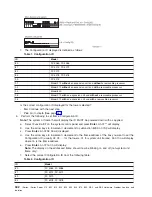
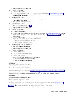
For
location
information
and
links
to
the
remove
and
replace
procedures,
see
or
.
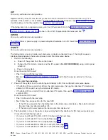
IDPART
For
use
by
authorized
service
providers.
A
system
unit
part
is
failing.
Follow
the
instructions
for
the
model
you
are
working
on:
v
Models
270,
820,
830,
840,
SB2,
or
SB3
(See
page
v
Models
800,
810,
825,
870,
or
890
(See
page
Instructions
for
Models
270,
820,
830,
840,
SB2,
and
SB3
1.
Choose
from
the
following
options:
v
If
you
are
on
a
Model
270
or
820:
Continue
with
the
next
step.
v
If
you
are
on
a
Model
830,
840,
SB2,
or
SB3:
Go
to
step
7
(See
page
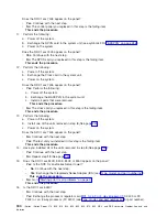
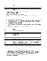
2.
Does
the
SRC
1xxx
840D,
840E
or
840F
appear
on
the
panel?
v
Yes
:
Continue
with
the
next
step.
v
No
:
Go
to
This
ends
the
procedure.
3.
Is
the
SRC
for
an
xSeries
(TM)
Server
Tower?
v
No
:
Continue
with
the
next
step.
v
Yes
:
Exchange
the
Integrated
xSeries
Adapter
(IXA)
(see
).
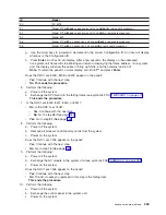
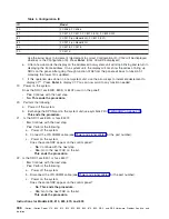
4.
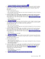
Perform
the
following
to
display
the
Configuration
ID:
Note:
The
system
or
frame
that
will
display
the
ID
MUST
be
powered
down
with
ac
applied.
If
you
are
working
on
a
Model
270
with
an
FC
7104
system
unit
expansion,
verify
that
both
the
ac
line
cord
for
the
system
and
the
ac
line
cord
for
the
expansion
unit
is
plugged
in.
a.
Select
Function
07
on
the
system
control
panel
and
press
Enter
.
An
07**
displays.
b.
Use
the
arrow
keys
to
increment
/
decrement
to
subfunction
A8
.
An
07A8
will
display.
c.
Press
Enter
.
An
07A8
00
will
display.
d.
Use
the
arrow
keys
to
increment
/
decrement
to
the
frame
address
of
the
box
you
want
to
check
(usually
02,
03,
...
for
the
towers,
01
for
system
unit
frames).
An
07nn
will
display
where
nn
is
the
frame
address.
e.
Press
Enter
.
An
07nn
00
will
display.
Note:
For
a
non-system
unit
frame,
the
display
on
the
addressed
frame
should
now
be
blinking
on
and
off.
For
a
system
unit,
press
an
arrow
key
(increment
or
decrement)
twice
to
display
the
ID
(first
07**
will
be
displayed
then
07nn
will
be
displayed,
where
nn
is
the
Configuration
ID).
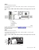
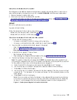
Figure
1.
Control
panel
diagram
for
function
A6
and
A8
Analyze
hardware
problems
341
Содержание iSeries Series
Страница 2: ......
Страница 504: ...492 iSeries iSeries Server 270 800 810 820 825 830 840 870 890 SB2 and SB3 Hardware Problem Analysis and Isolation...
Страница 508: ...496 iSeries iSeries Server 270 800 810 820 825 830 840 870 890 SB2 and SB3 Hardware Problem Analysis and Isolation...
Страница 511: ......
Страница 512: ...Printed in USA SY44 5914 01...

